78
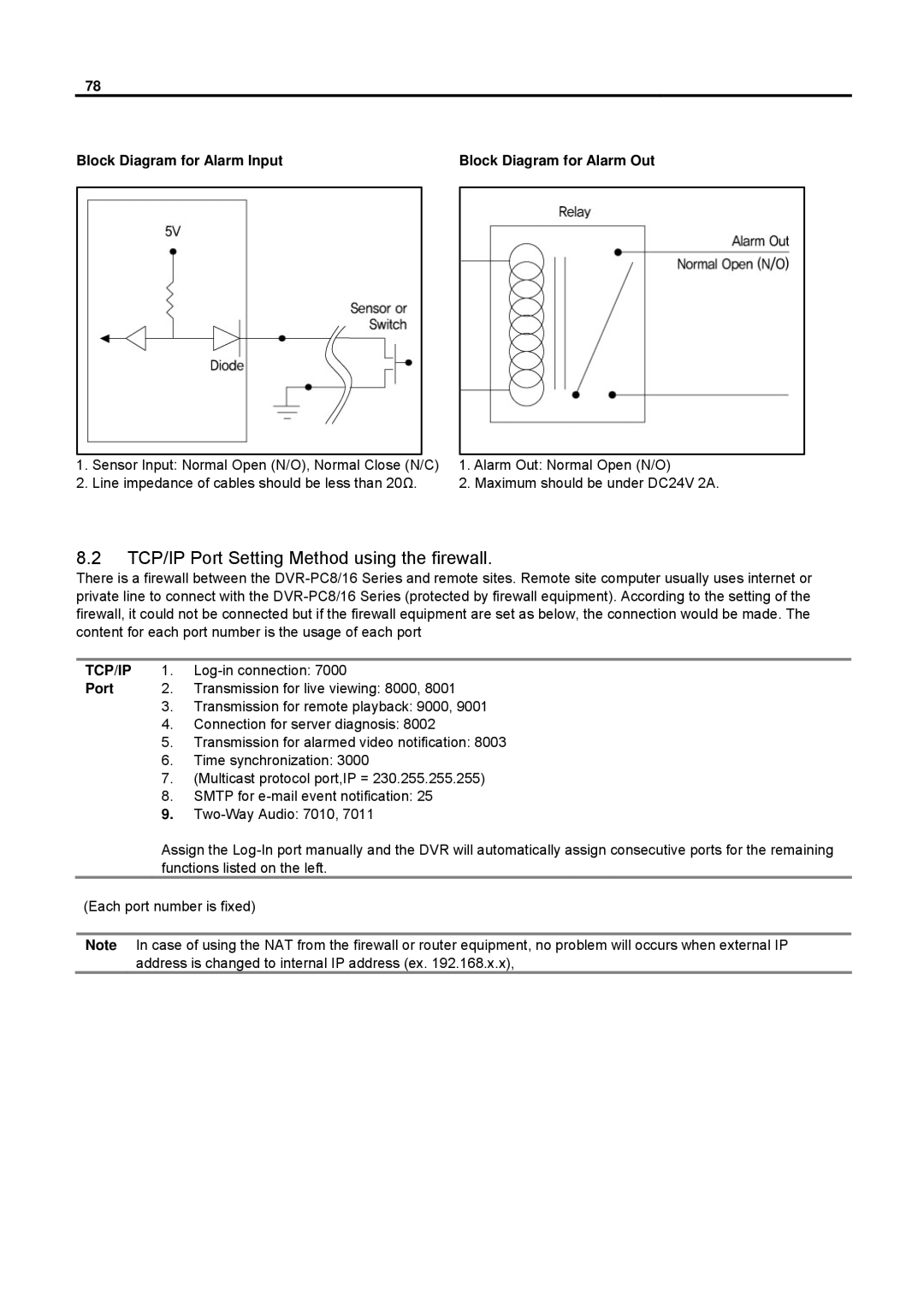
Block Diagram for Alarm Input | Block Diagram for Alarm Out |
1. | Sensor Input: Normal Open (N/O), Normal Close (N/C) | 1. Alarm Out: Normal Open (N/O) |
2. | Line impedance of cables should be less than 20Ω. | 2. Maximum should be under DC24V 2A. |
8.2TCP/IP Port Setting Method using the firewall.
There is a firewall between the
TCP/IP 1.
Port 2. Transmission for live viewing: 8000, 8001
3.Transmission for remote playback: 9000, 9001
4.Connection for server diagnosis: 8002
5.Transmission for alarmed video notification: 8003
6.Time synchronization: 3000
7.(Multicast protocol port,IP = 230.255.255.255)
8.SMTP for
9.
Assign the
(Each port number is fixed)
Note In case of using the NAT from the firewall or router equipment, no problem will occurs when external IP address is changed to internal IP address (ex. 192.168.x.x),