Binary Solvent Delivery Module
Operators Manual
Page
1.INTRODUCTION
1.1.1 Pump Features
fFast & easy setup
1.1.2 Wetted Pump Materials
1.1.3 Self-FlushingPump Head
Microprocessor advanced control
1.1.4 Self-Flushand Seal Life
It is recommended that the Self Flush feature be used to improve seal life in a number of applications. In particular, as stated above if pumping Buffers, Acids/Bases or any inorganic solution near saturation, the pump should utilize the Self Flush feature. With every piston stroke, an extremely thin film of solution is pulled back past the seal. If this zone is dry without use of Self Flush, then crystals will form with continuous operation, which will ultimately damage the seal
Flow Rates
2.2Location/Environment
2.INSTALLATION
2.1Unpacking and Inspection
2.3Fluid Connections & Priming
Connect wash solution inlet and outlet tubing
SELF-FLUSH
PUMP
opaque to the flush housing as shown
2.5.1 Solvent Out-gassingand Sparging
2.4Electrical Connection
2.5Solvent Preparation
2.5.3 Filtration
2.6.1Mobile Phase Reservoirs
2.5.2 Cavitation
2.5.4 Initial system pressurization Daily
2.6.4 Priming the Pump and the Flushing Lines
2.6.2 Self-FlushSolution
2.6.3 Inlet Tubing and Filters
2.6.6 Long Term Pressure Calibration Accuracy
2.7.1Isopropanol Flush
2.7.2 Packaging for Shipping
2.7Preparation for Storage or Shipping
3.OPERATION
3.1.1Control Panel
Non-volatileMemory Reset If the pump is operating erratically, there is the possibility that the memory has been corrupted. To reset the memory and restore the pump to its default parameters, press and hold the UP-ARROWbutton when the power is switched on. Release the button when the display reads rES. The parameters stored in non-volatilememory, i.e., the flowrate, the pressure compensation, the voltage/frequency select, the lower pressure limit, and the upper pressure limit will be set to the factory default values. The head type setting is the only parameter not changed by the non-volatilememory reset function. If the firmware is upgraded to a newer version, a non- volatile memory reset will automatically occur the first time the power is switched on
3.6Symbols
3.5Rear Panel Remote Input
4.1.2 Pump Cycle
4.THEORY OF OPERATION
4.1.1Liquid System Flow Path
4.1.3 Pulse Damping
4.2.3 Remote Interfacing
4.2.2 DC Power Supply
4.2.1 Microprocessor Control
4.2.4 Motor Stall Detector
Page
5.2.1Removing a Pump Head
5.MAINTENANCE
5.1.1 Inlet Filters
5.1Filter Replacement
3.Remove the inlet line from the inlet check valve
OUTLET FLUSHING CHECK VALVE
OUTLET FLUSHING
5.2.2 Cleaning the Pump Head Assembly
1.Inspect the piston seal cavity in the pump head. Remove any foreign material using a cotton swab, or equivalent, and avoid scratching the sealing surfaces. Repeat for the self-flushhousing. Be sure no fibers from the cleaning swab remain in the components
3.If the check valves have been removed, tighten the check valves on stainless steel pumps to 75 inch-poundsor enough to seal at maximum pressure. Do not exceed maximum torque. For Bioclean PEEK pumps, tighten each check valve firmly by hand. Do not go ¼ turn past finger tight
5.2.3 Replacing Piston Seals
Lower than normal pressure, pressure variations, and leaks in the pumping system can all indicate possible problems with the piston seal. Depending on the fluid or mobile phase used, piston seal replacement is often necessary after 1000 hours of running time
1.Remove the pump head as described in Section 5.2.1. Use caution so as not to damage the sapphire piston
5.2.4 Changing the Piston
5.Condition the new seal as described in Section
5.2.5Replacing the Pump Head
5.3Conditioning New Seals
5.4Check Valve Cleaning and Replacement
5.5.1Removing the Pulse Damper
5.5.2 Pulse Damper Refurbishing
5.5Pulse Damper Replacement
5.5.3 Pulse Damper Installation
5.6Cleaning the Pump
5.8Other Pump Maintenance
5.7Lubrication
7-14
5.9Fuse Replacement
1.Unplug the unit 2.Remove the cover
You Notice
6.PROBLEM SOLVING
Quick Guide to Problem Solving
This May Mean
7.LIST OF REPLACEMENT PARTS
880201 Seal Kit, Aqueous, 5mL
Part Description
APPENDIX A
A.1.1 Hardware Implementation
Part Number
Command Interpreter
A.1.3
“/” character
Page
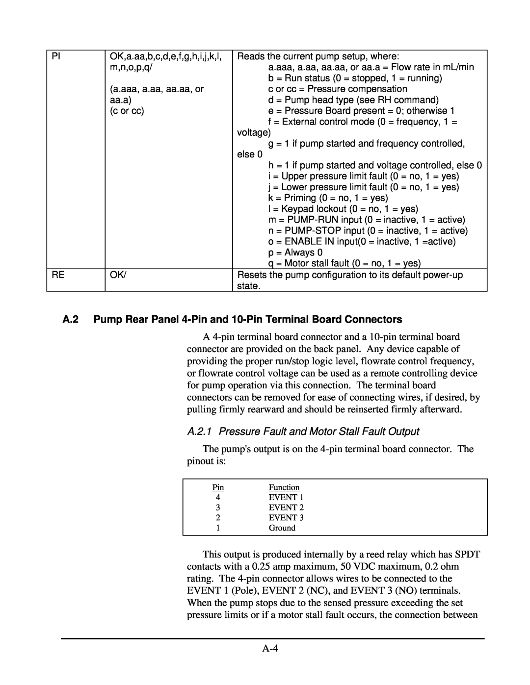
A.2.1 Pressure Fault and Motor Stall Fault Output
A4-pinterminal board connector and a 10-pinterminal board connector are provided on the back panel. Any device capable of providing the proper run/stop logic level, flowrate control frequency, or flowrate control voltage can be used as a remote controlling device for pump operation via this connection. The terminal board connectors can be removed for ease of connecting wires, if desired, by pulling firmly rearward and should be reinserted firmly afterward
A.2.2 General Information on Inputs
the EVENT 1 terminal and the EVENT 2 and EVENT 3 terminals is affected. EVENT 2 is Normally Closed connected to EVENT 1 until a fault occurs and then opens. EVENT 3 is Normally Open not connected to EVENT 1 until a fault occurs and then closes
A.2.4 Run and Stop Inputs
The PUMP-RUN, PUMP-STOP,and ENABLE IN inputs operate from an internal 5 VDC source and each one draws approximately 0.008 amps when connected to COM. To activate either the PUMP- RUN, PUMP-STOP,or ENABLE IN input connect it to COM. Any device capable of switching 0.008 amps can be connected between the PUMP-RUN, PUMP-STOP,or ENABLE IN input and COM, such as: a switch contact, a relay contact, an open collector output, an open drain output, or any output with a high logic level output of 3.8 to 6.0 volts and a low logic level output of 0.0 to 0.5 volts. A switch contact or a relay contact is preferred since this type of connection will provide isolation between the pump and the controlling device. The COM terminal is internally connected to the pumps chassis ground and should be connected to the controlling devices ground or zero volt terminal when the controlling device has an open collector output, an open drain output, or any output with logic level output
A.2.4 Enable Input
When activated ENABLE IN is at a low logic level, the ENABLE IN input disables flowrate control on the front panel and enables flowrate control on the back panel
APPENDIX B
EZ GRIP FITTING GUIDE
Scientific Systems Inc Warranty Statement
A-10