CPF180i CPF300i
FCC Compliance Statement
Cleaning Procedure for the GPS Chart Plotter Screen
CPF180i and CPF300i
Table of Contents
MAP Functions
Find Services
Optional C-MAP by Jeppesen MAX Cartography Overview
Creating Marks
Tracks
Pages
101
AIS
Mobilarm
Fish Finder
Appendix Terms
Specifications
Technical Tests
Analitycal Index
CPF180i and CPF300i
Introduction
General Information
Packing List
1 CPF300i Packing List
Optional Accessories
0 CPF180i Packing List
Optional Dome or Open Array Radar Antennas
CPF180i and CPF300i
CPF180i and CPF300i
Installation
Mounting the GPS Chart Plotter
Bracket Mounting
Flush Mounting
Example of Flush installation CPF180i
Mounting the Optional External GPS Antenna
0 Installing the External GPS Antenna
Flush mounting the antenna
Connection Table For CPF180i
Power Data Cable and Nmea PWR & ACC 1 Cable
Connections
Smart GPS Cable
Connection For CPF180i 2.4.1.1 DC Power Connection
AIS Setup
Connection of the AIS receiver, VHF and Autopilot
Connection Table For CPF300i
12VDC Power and Nmea PWR & ACC 1 Cable
DC Power Connection
Connection For CPF300i
Battery Connections
Nmea Connections
Connection a VideoCamera, AIS receiver, VHF and Autopilot
Personal Computer Connections
GPS Position on a VHF Radio
Radar Antenna USA only
Other DSC VHF Manufactures
11 CPF3000i Video Input
Video Connector
Nmea Data
Video Camera Input
II. Quick Activation by pressing CLR for 1 second
VCR or DVD Input
From the menu
III. Quick Activation by Soft Keys
Demo Mode for Dealer USE
Controls and Indicators
Controls and Connections
Power On, Off and ShuttlePoint knob operation
CPF300i Soft Keys
Getting Started
Cursor Vs. Home Mode
Cursor Mode
Home mode
Cursor and Menu selection speed
Changing the Ships Icon
Changing the backlight and contrast
Selecting North Up or Course Up
Adjusting Time
Automatic Time
Changing the Chart Color
Selecting Loran TD or Other Coordinate System
Selecting Language
Display Color menu
Selecting Pages Using Soft Keys on CPF300i
Customizing the Soft Keys on CPF300i
Other Settings in General Setup Menu
RADAR/FISH Finder
Information
Ship Icon
CPF180i and CPF300i
Port Services
Find Services
Using Find Services & More Functions
Port
Tide Stations
1 Find a Port
Wrecks
Obstructions
Lakes Information
Quick Info On Lakes
Lakes By Name
Full Info On Lakes
Points Of Interest
6 Find Lakes By Name
User Points
Coordinates
9 Find GPS Coordinates
Data Features
Optional C-MAP by Jeppesen MAX Cartography Overview
Inserting the C-CARD
Presentation Features
Cartographic Data related Features
MAX and NT/NT+ C-CARD coexistence
Zoom Type
MAP Functions
MAX Functions Menu
Place Names size
Perspective View
Dynamic Nav-Aids
Safety Status Bar
Scale
Satellite Imagery
Currents Prediction
Chart Language
To 0.1 kn To 1.0 kn To 2.0 kn To 3.0 kn To 9.9 kn
Language
Pictures & Diagrams
How to show the pictures or diagrams of a Multimedia Object
Mode
Enhanced Port Info
8b Example of Full Info
CPF180i and CPF300i
Editing a Mark
Creating a NEW Mark Using the Chart
Creating Marks
Mark
Deleting a Mark or Waypoint
Moving a Mark or Waypoint
MARKS/WAYPOINTS List
Find
Creating a NEW Mark with the User Points List
Goto Cursor
Goto Cursor
Goto Mark
Goto Route
CPF180i and CPF300i
MAN Over Board MOB Function
Deleting a MOB Point
CPF180i and CPF300i
Creating a Route Using Waypoints
Routes
Creating a Route Using Marks on the Chart
Making Additional Routes
By select Route
Inserting a Waypoint Into a Route
Goto a Route
By Cursor key
Other Settings in Route Menu
Used when following the Route
Route Checking
Tracks
Tracking
Saving and starting a new Track
Other Settings in Track Menu
Using the Trip LOG
ENT
Resetting the Trip Log
CPF180i and CPF300i
Formatting the User C-CARD
User C-CARD
User C-CARD Menu
Transferring files to the optional User C-CARD
Loading a file
Deleting a file from the User C-CARD
Refreshing the User C-CARD
Pages
Selection by Menu
Selection by Soft KEY only for CPF300i
Chart
Screen display pages by Soft Keys on CPF300i
Window Selections
Customizing the Data Windows
Trip Log selection / Reset
Additional Functions on Chart
Display Mode
Turning Off Information on Icon Points
Marine Settings
Depth Settings
Land Settings
Chart Settings
Underwater Objects Settings
Customizing Chart Settings
Navigation
Time To Go
Highway
Celestial
Course over ground Bearing Highway Display Highway Scale
GPS Status
Used Satellite COG Course Over Ground
WAAS/EGNOS Setting
GPS Setup Menu
Nmea Display
Changing the Nmea page Windows
Nmea Display
Nmea Trend Pages
VHF Digital Selective Calling
Interfacing
DSC Distress Call
Position Request
Navigate
Advanced Settings
INPUT/OUTPUT Nmea
Coordinate System
Alarms
Loran TD
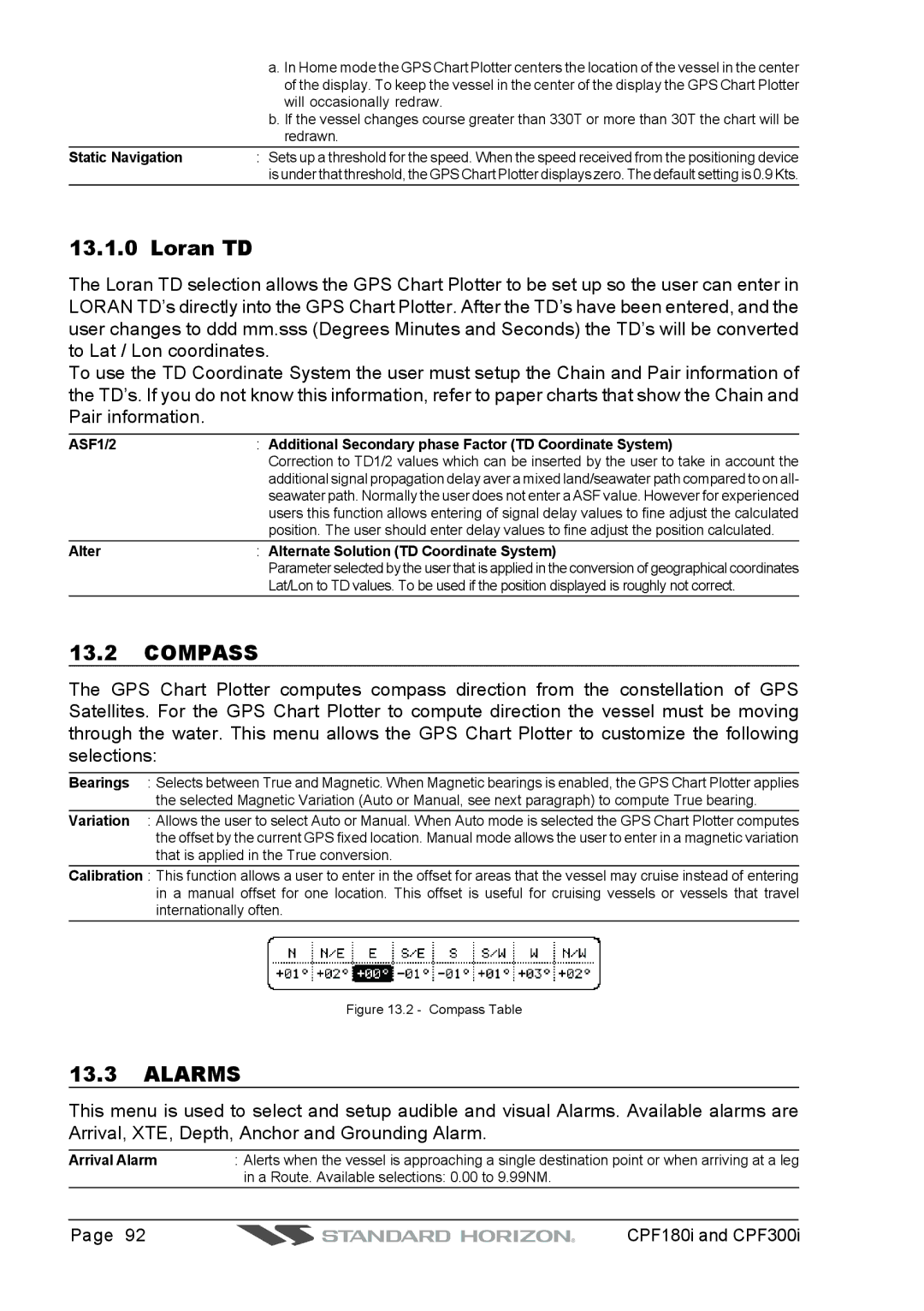
Compass
Simulation
Navigating a Route in Simulation mode
DSC Polling
AIS
AIS System Definitions
To SET the Chart Plotter for Receiving AIS
AIS Menu
Quick Info on AIS Target
AIS List
· SOG · COG
CPF180i and CPF300i
Weather Service
Weather Service Menu
Download
Real Time View
Copy From User C-CARD
Weather Forecast
Type of Data
MOBILARM-GPS Chart Plotter Connection
Mobilarm
Connection Example
Mobilarm Status
Software Setup
Chart Plotter
Port 1 Example
Mobilarm MOB alert is received
Signal Lost
Mobilarm PTX
Connected
Placing Cursor on the PTX Icon
0a Example of PTX warning window on CP300
On CPF180I
Delete PTX
Goto PTX
On CPF300I
Mobilarm Alarm Status List
1a Example of Goto PTX on CP300
PTX number
Menus/data pages if open and center the chart selected PTX
Centers the chart on the selected PTX
This page allows you to
CPF180i and CPF300i
Fish Finder
Fish Finder working principle
Understanding the Fish Finder
Fish Finder window
Deep Alarm Bar
Water Temperature
Shallow Alarm Bar
Color Bar
Understanding the Fish Finder display
Displaying the Fish Finder
Auto Full
17.2.3 200 kHz and 50 kHz Fish/Chart Pages
17.2.2 200 kHz and 50 kHz Zoom Pages
Radar Pages Except CPF180I
Focus Soft Key on FISH/CHART Page Except CPF180I
FISH/RADAR/CHART
Radar Combo
Soft KEY Operation Except CPF180I
Focus Soft Key
Fish Finder Setup Menu
Presets
Manual Mode
Gain Mode
Auto Mode
Frequency
Depth
Range Mode
Range Menu
Shift
Interference Rejection
Gain
Sensitivity Menu
STC Length
STC Strength
Display Setup
Surface Noise Filter
OFF
Scrolling Speed
Color Settings
Fish Symbols
White Line
Keel Offset
Transducer Setup
Scope
Calibrate Water Speed
Temperature Upper
Set Defaults
Alarms
Temperature Lower
Load Settings from User C-CARD
Temperature Rate
Save Settings to User C-CARD
Restore Current Preset Defaults
16 C-Card Restore settings
CPF180i and CPF300i
Trouble Shooting
CPF180i and CPF300i
System Test
RAM Menu reset
Technical Tests
DIM Menu
Cartridges
Serial Ports
Specifications
20.0 CPF180i Specifications
MAP B Y J Eppesen NT +/MAX C-CARD
VHW, WPL, RTE
20.1 CPF300i Specifications
RMA, RMB, RMC, GGA, HSC, DBT, DPT, MTW
HDT, RMC, VHW, VTG, DPT, DBT, MTW, VWR
FF Module Specifications
Optional Waas GPS Receiver Specifications
CPF180i and CPF300i
Appendix Terms
Units
Page
CPF180i and CPF300i
Analitycal Index
Auto Info
Goto
GPS
HDG Hdop
Nmea
MOB Mobilarm Mounting
Pictures & Diagrams
Radar
Waas
Please Note
A N D a R D H O R I Z O N L I M I T E D W a R R a N T Y