LC-1021
EC Council Directive 73/23/EEC and 93/68/EEC of 22 July
About this manual
Chapter
Contents
Using the EDS Mode
Using the Printer with MS-DOS
Optional Accessories
Paper Handling
Page
Printer Setup
Choosing a place for the printer
Unpacking the printer
General guide
Opening the front cover
Removing the protective materials
Removing the protective materials
Installing the platen knob
Installing the ribbon cassette
Installing the ribbon cassette
Removing the ribbon cassette
Installing the paper guide
Installing the paper guide
Paper Type Paper Guide Angle
Standing up the paper guide
Degree angle Fanfold paper Degree angle Cut-sheet paper
Connecting to a power outlet and turning power on and off
Loading fanfold paper
Loading fanfold paper
Printer Setup
Loading fanfold paper
Printing on fanfold paper
Cut-sheet paper
Parking fanfold paper
Unparking fanfold paper
Using the tear-off function
Connecting to your computer
Connecting to your computer
Switching between on-line and off-line
Control Panel Operations
Selecting a font
Entering the Font Lock Mode
Lit Indicator Font
Lit Indicators Meaning
Setting the character pitch
Entering the Pitch Lock Mode
Line feed
Paper eject cut-sheet paper
Form feed fanfold paper
Micro feed
Tear-off function fanfold paper
Setting the top of form position
Selecting the Quiet Print Mode
Changing the auto load position
Changing the auto load position
Saving a macro
Clearing the printer’s buffer
Entering the Multi-part Mode
Initializing the printer
Entering the EDS Mode
Using the EDS Mode
About EDS Mode settings
Selecting a switch
Changing a switch setting
Lit Indicator Selected Bank
Lit Indicator Selected Switch
Exiting the EDS Mode
Printing the current switch settings
Checking the settings of switches in a bank
EDS Mode Settings
Switch 6 Multi-Part Mode
Switch 1 Graphics Direction
Switch 2 Auto Tear-off Long
Switch 3 Line Spacing
Switches 1, 2 Print Mode
Switches 3, 4, 5 Print Pitch
Switch 6 Quiet
Print Mode
Length
Switches 1, 2, 3, 4 Page Length
Switch 5 Reserved Switch 6 Reserved
Code
SW1 SW2 SW3 SW4 SW5
Name Country Remarks
Country Remarks
International
Character Set
Switches 1, 2, 3, 4, 5 NLQ Font Selection
Bank F
Using the Printer with MS-DOS
Setting up for printing with MS-DOS
Paper Handling
Selecting paper types
Cut-Sheet Paper Manual Feed
Cut-Sheet Paper with Optional Automatic Sheet Feeder
Adjusting for paper thickness
Labels
Thickness
Automatic fanfold feeding
Manual sheet feeding
Clearing paper jams
Preparing the printer
Optional Accessories
Automatic Sheet Feeder SF-10HA
Pull Tractor Unit PT-10HA
Serial Interface Unit IS-8H192
Specifications IS-8H192
Serial-to-Parallel Converter SPC-8K
Specifications
Short test
Appendix a Troubleshooting
Testing the printer
Hexadecimal dump
Long test
Adjusting the dot alignment
DOT Adjustment Setting Draft
Troubleshooting guide
Problem Possible Cause
Troubleshooting guide
Printed on Return is enabled
Printer case is hot Printer’s air vents are
Left margin moves to Paper is not loaded
Enter the EDS Mode
Checking system software settings in Windows
To check the default printer selection
To check the driver setup
To check the application printer selection
Checking system software settings in MS-DOS
To check the port
Appendix B Specifications
Dimensions and Weight
Power Supply
Power Consumption
Fanfold with push tractor feeder
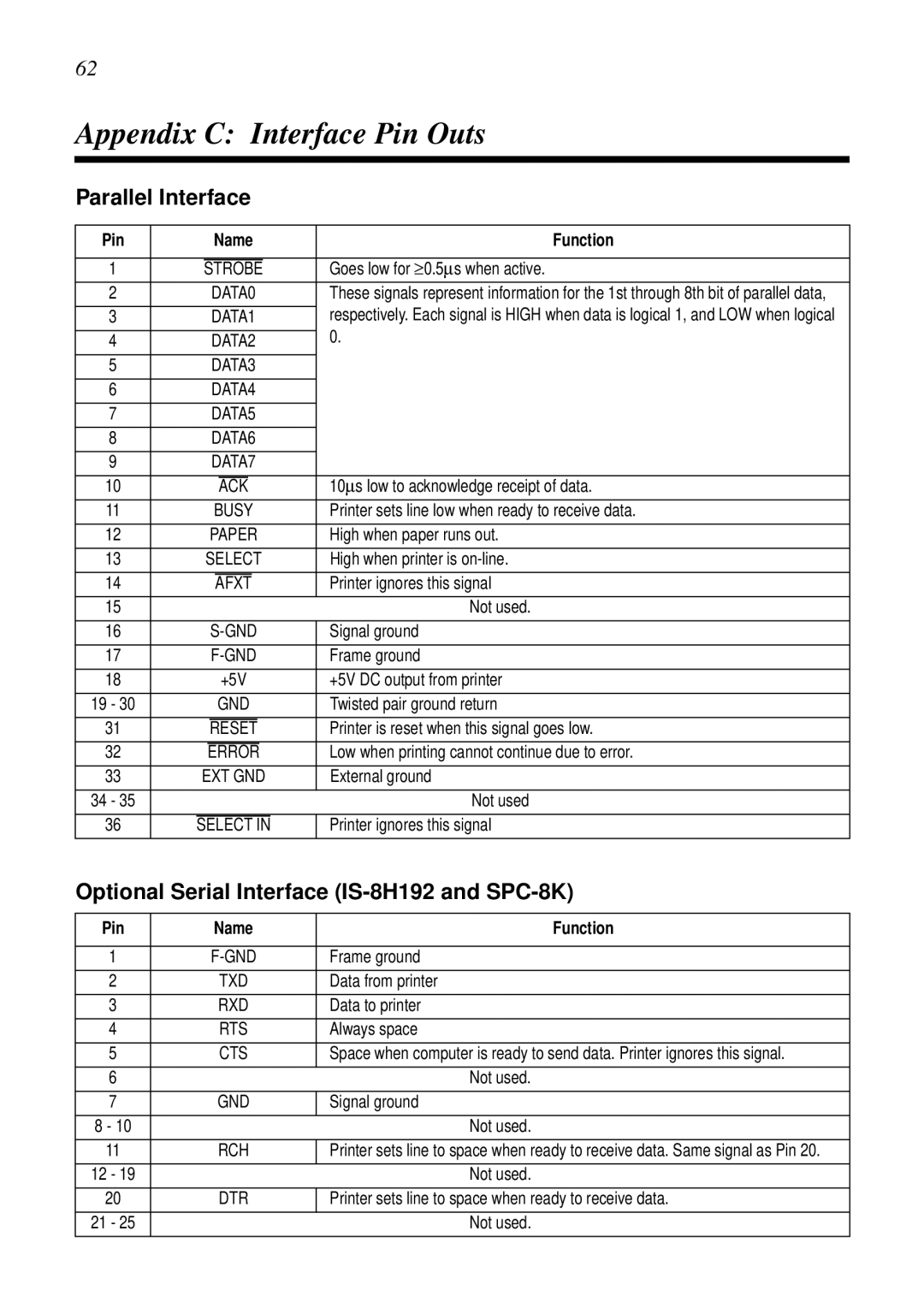
Appendix C Interface Pin Outs
Parallel Interface
Optional Serial Interface IS-8H192 and SPC-8K
Pin Name Function
Appendix D Character Sets
Standard Italic Character Set #2 International Character Set
IBM Character Set #2 Code Page #437 IBM-PC Character Set #1
IBM Special Character Set
Code Page #860 Portuguese
Code Page #850 Multi-lingual
Code Page #861 Icelandic
Code Page #863 Canadian French
Code Page #866 Russian
Code Page #865 Nordic
Code Page #3840 IBM-Russian
Code Page #3841 Gost-Russian
Code Page #3844
Code Page #3843 Polish
Code Page #3845 Hungarian
Code Page #3846 Turkish
Code Page #3848 Brazil-ABICOMP
Code Page #3847 Brazil-ABNT
Code Page #852 Latin-2
Code Page #851 Greek
Code Page #1001 Arabic
Code Page #737 Greek
Code Page #869 Greek
Code Page #2001 Lithuanian-KBL
Code Page #928 Greek
Code Page #772 Lithuanian
Code Page #774 Lithuanian
Code Page #3002 Estonian2
Code Page #3001 Estonian1
Code Page #3011 Latvian1
Code Page #3012 Latvian2
Code Page #3031 Hebrew
Code Page #3021 Bulgarian
Code Page #3041 Maltese
Appendix E Printer Control Codes
Font and Character Set Control Commands
Description Mode Ascii Code
Print Pitch Control Commands
Top/Bottom Margin and Vertical Tab Commands
Form Feed and Related Commands
Special Print Mode Commands
Bit Image Graphic Commands
Horizontal Print Position Control Commands
Line Spacing Commands
Download Character Commands
Other Commands
ESC U1
Appendix F Glossary
Appendix G Control Panel Operation Guide
A1 D4 B2 E5
Page
MS-DOS
Page
MS-DOS
Page
Worldwide Headquarters