Manuals
/
Star Micronics
/
Computer Equipment
/
Printer
Star Micronics
TSP1000
user manual
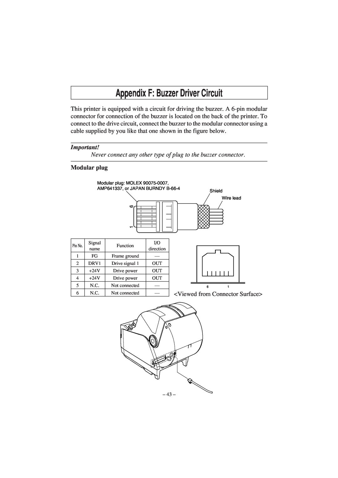
Appendix F Buzzer Driver Circuit, Modular plug
Models:
TSP1000
1
47
52
52
Download
52 pages
58.91 Kb
44
45
46
47
48
49
50
51
Specifications
Install
Errors
Connecting USB Cable
D-1. RS-232C Connector
Periodical Cleaning
Non recoverable error
Turning Power On
Switch Blind Installation
Page 47
Image 47
Page 46
Page 48
Page 47
Image 47
Page 46
Page 48
Contents
USER’S MANUAL
TSP1000 SERIES
THERMAL PRINTER
Page
Radio Interference Regulations
Federal Communications Commission Radio Frequency Interference
Statement
Statement of The Canadian Department of Communications
TABLE OF CONTENTS
1-1. Unpacking
1. Unpacking and Installation
2. Parts Identification and Nomenclature
Choosing a place for the printer
Core inner
3. Consumable Parts and AC Adapter
Core outer
Page
4-1-1. Serial Interface RS-232C Cable
4. Connecting Cables and AC Adapter
4-1. Interface Cable
5 cm maximum Fastener Pull and cut
4-1-2. Parallel Interface Cable
Ferrite core Interface cable
Parallel interface cable
4-1-3. Connecting USB Cable
10cm
4-1-4. Connecting Ethernet Cable
Ethernet cable
Ferrite core
4-2. Connecting to a Buzzer Drive
4-3. Connecting the Optional AC Adapter
Make sure that the AC adapter has been connected as described in
4-4. Turning Power On
Install the cable as shown in the diagram below
4-5. Installing the Cable
4-6. Switch Blind Installation
5-1. Control Panel
Errors
5. Control Panel and Other Functions
4 Paper detection error
3 Non recoverable error
1 If a non recoverable error occurs, turn the power OFF immediately
5-3. Self Printing
1 Push the Cover open lever, and open the printer cover
6. Loading the Roll Paper
Be sure to use roll paper that matches the printer’s specification
Note Make sure that the printer cover is securely closed
1. Do not touch the cutter blade
7. Adjusting the Near-end Sensor
Adjustment value according to the paper you are using
8-2. Removing Paper Jam
8. Preventing and Clearing Paper Jams
8-1. Preventing Paper Jams
8-3. Releasing a Locked Cutter
1 Do not apply extreme pressure to the moving blade
6 Install the front cover, and then set the power switch to ON
9-2. Cleaning the Paper Holder
9. Periodical Cleaning
9-1. Cleaning the Thermal Head
A-1. General Specifications
Appendix A Specifications
A-5. Option
A-2. Auto Cutter Specifications
A-4. Electrical Characteristics
A-3. Interface
1.0 million cuttings if the paper thickness is 100 µm
A-6. Environmental Requirements
A-7. Reliability
20 million lines based on an average printing rate of
Remarks
A-8. Black Mark Specifications
Appendix B Dip Switch Setting
No. 1 2 3 DIP-SW2
B-1. Parallel Interface Model
No. 1 2 3 4 5 6 7 DIP-SW1
B-2. Sperial Interface RS-232C Model
DIP-SW3
DIP switch
Printer Driver URL
B-3. USB Interface Model
B-4. Ethernet Interface Model
LED Display
Installing the Printer Driver and the LPR Port Driver Set
Green Lights when other party connection is recognized as 10BASE-T
Orange Lights when packets are received
Appendix C Parallel Interface
Table of Connection Signals for Each Mode
Appendix D Serial Interface RS-232C
D-1. RS-232C Connector
DIP SW
D-sub 25 Pin
D-sub 9 Pin
Printer status
D-sub 25 pin
D-3. Electrical Characteristics
D-2. Cable Connections
Host side
Appendix E USB Interface and Ethernet Interface
E-1. USB Interface Specifications
E-2. Ethernet Interface Specifications
Modular plug
Appendix F Buzzer Driver Circuit
Drive circuit
Appendix G Memory Switch Settings
Page
Page
OVERSEAS SUBSIDIARY COMPANIES STAR MICRONICS AMERICA, INC
Top
Page
Image
Contents