PRINCIPLES OF OPERATION
DO1 DO2 DO3 | DO62 DO63 DO64 | ||||||||||||
|
|
|
|
|
|
|
|
|
|
|
|
|
|
|
|
|
|
|
|
|
|
|
|
|
|
|
|
GNDH
VDD
BUFFER
GNDL
VDD
CHECKER
VDD
STB |
|
|
|
|
|
|
|
|
BEO |
|
|
|
|
|
|
|
|
| Q | Q | Q | LATCH Q | Q | Q |
| |
| L | L | L |
| L | L | L |
|
| D | D | D |
| D | D | D |
|
LAT |
|
|
|
|
|
|
|
|
CTL |
|
|
|
|
|
|
|
|
SI | D Q | D Q | D Q | SHIFT | D Q | D Q | D Q | SO |
|
|
|
|
|
|
|
| |
| C | C | C | REGISTER | C | C | C |
|
|
|
| ||||||
CLK |
|
|
|
|
|
|
|
|
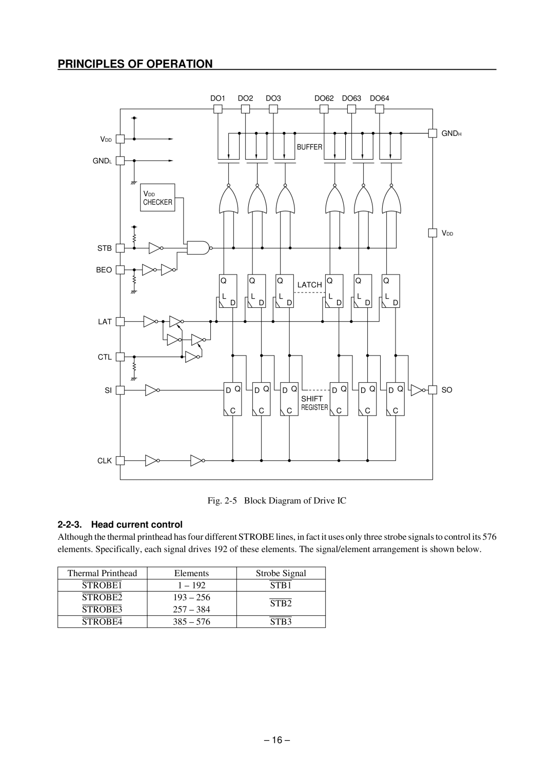
Fig. 2-5 Block Diagram of Drive IC
Although the thermal printhead has four different STROBE lines, in fact it uses only three strobe signals to control its 576 elements. Specifically, each signal drives 192 of these elements. The signal/element arrangement is shown below.
Thermal Printhead | Elements | Strobe Signal | |||||
|
|
|
|
|
|
| |
|
|
| 1 – 192 |
|
|
| |
STROBE1 | STB1 | ||||||
|
|
| 193 – 256 |
|
|
| |
STROBE2 |
|
|
| ||||
|
|
| STB2 | ||||
|
|
|
|
| |||
STROBE3 | 257 – 384 | ||||||
|
|
| |||||
|
|
| 385 – 576 |
|
|
| |
STROBE4 | STB3 | ||||||
– 16 –