PRINCIPLES OF OPERATION
2-4. Power-On Reset Circuit
The
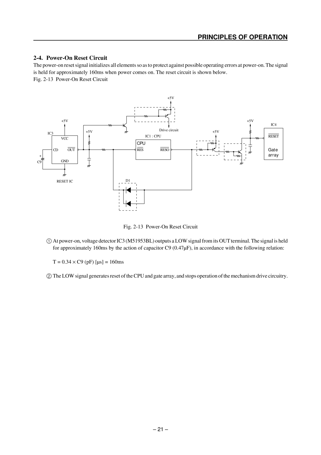
Fig. 2-13 Power-On Reset Circuit
+5V
+
C9
| +5V |
IC3 | +5V |
| |
| VCC |
CD | OUT |
| GND |
Drive circuit IC1 : CPU
CPU
![]() RESRESO
RESRESO ![]()
+5V
+5V
IC4
RESET
Gate array
RESET IC
D1
Fig. 2-13 Power-On Reset Circuit
1At power-on, voltage detector IC3 (M51953BL) outputs a LOW signal from its OUT terminal. The signal is held for approximately 160ms by the action of capacitor C9 (0.47µF), in accordance with the following relation:
T = 0.34 × C9 (pF) [µs] = 160ms
2The LOW signal generates reset of the CPU and gate array, and stops operation of the mechanism drive circuitry.
– 21 –