PRINCIPLES OF OPERATION
2-2. Data Arrangement and Printing
2-2-1. Arrangement
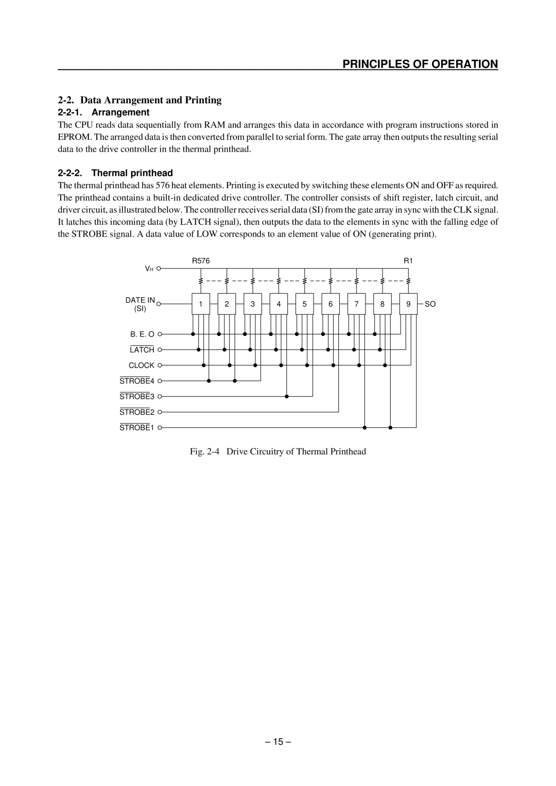
The CPU reads data sequentially from RAM and arranges this data in accordance with program instructions stored in EPROM. The arranged data is then converted from parallel to serial form. The gate array then outputs the resulting serial data to the drive controller in the thermal printhead.
The thermal printhead has 576 heat elements. Printing is executed by switching these elements ON and OFF as required. The printhead contains a
VH ![]()
DATE IN
(SI)
B. E. O ![]()
LATCH ![]()
CLOCK ![]()
STROBE4 ![]()
STROBE3 ![]()
STROBE2 ![]()
STROBE1 ![]()
R576
1
2
3 | 4 | 5 |
6
7
8
R1
9
SO
Fig. 2-4 Drive Circuitry of Thermal Printhead
– 15 –
