PRINCIPLES OF OPERATION
STB1
STB2
STB3
HD ON
(B)
BEO
(Q)
Trigger
Retrigger | Retrigger |
tw
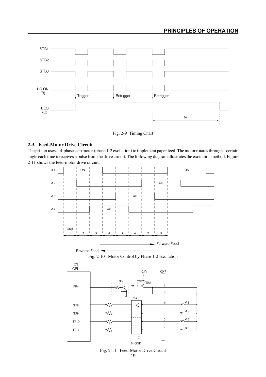
Fig. 2-9 Timing Chart
2-3. Feed-Motor Drive Circuit
The printer uses a
![]() 1
1
ON
ON
![]() 2
2
![]() 3
3
![]() 4
4
Step
1 2
ON
ON
ON
3 |
| 4 |
| 5 |
| 6 |
| 7 |
| 8 |
![]() Forward Feed
Forward Feed
Reverse Feed ![]()
Fig. 2-10 Motor Control by Phase 1-2 Excitation
IC1
CPU
PB4
TP8
TP9
TP10
TP11
| +24V | CN7 |
|
DT9 | TR5 |
|
|
| 1 |
| |
|
|
| |
|
| 2 |
|
| TA1 |
|
|
|
| 6 | 1 |
|
| 3 | 2 |
|
| 5 | 3 |
|
| 4 | 4 |
Fig. 2-11 Feed-Motor Drive Circuit
– 19 –
