PARTS REPLACEMENT
| 5 | 4 |
|
| |
7 |
|
|
|
| 3 |
|
| 2 |
1 |
|
|
|
| 6 |
|
| 1 |
|
| 2 |
3 |
| 5 |
4 |
|
|
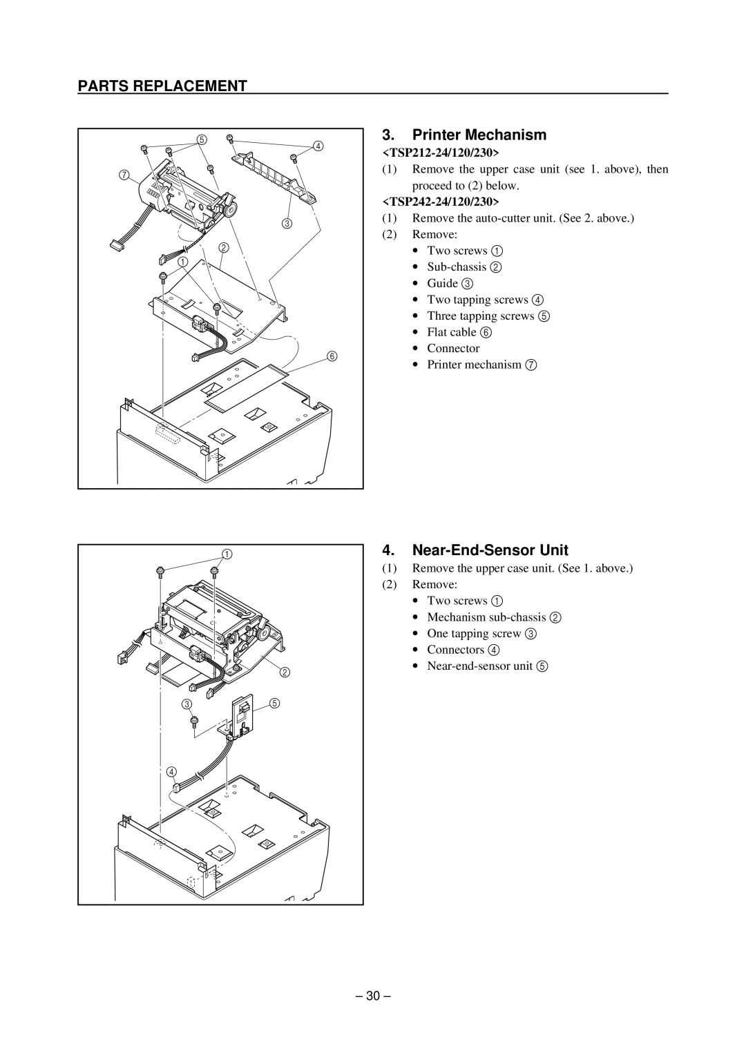
3.Printer Mechanism
(1)Remove the upper case unit (see 1. above), then
proceed to (2) below.
<TSP242-24/120/230>
(1)Remove the
(2)Remove:
∙Two screws 1
∙
∙Guide 3
∙Two tapping screws 4
∙Three tapping screws 5
∙Flat cable 6
∙Connector
∙Printer mechanism 7
4.Near-End-Sensor Unit
(1)Remove the upper case unit. (See 1. above.)
(2)Remove:
∙Two screws 1
∙Mechanism
∙One tapping screw 3
∙Connectors 4
∙
– 30 –
