PRINCIPLES OF OPERATION
CLOCK
SI
LATCH
COMMON STB1
STB2
STB3
24V
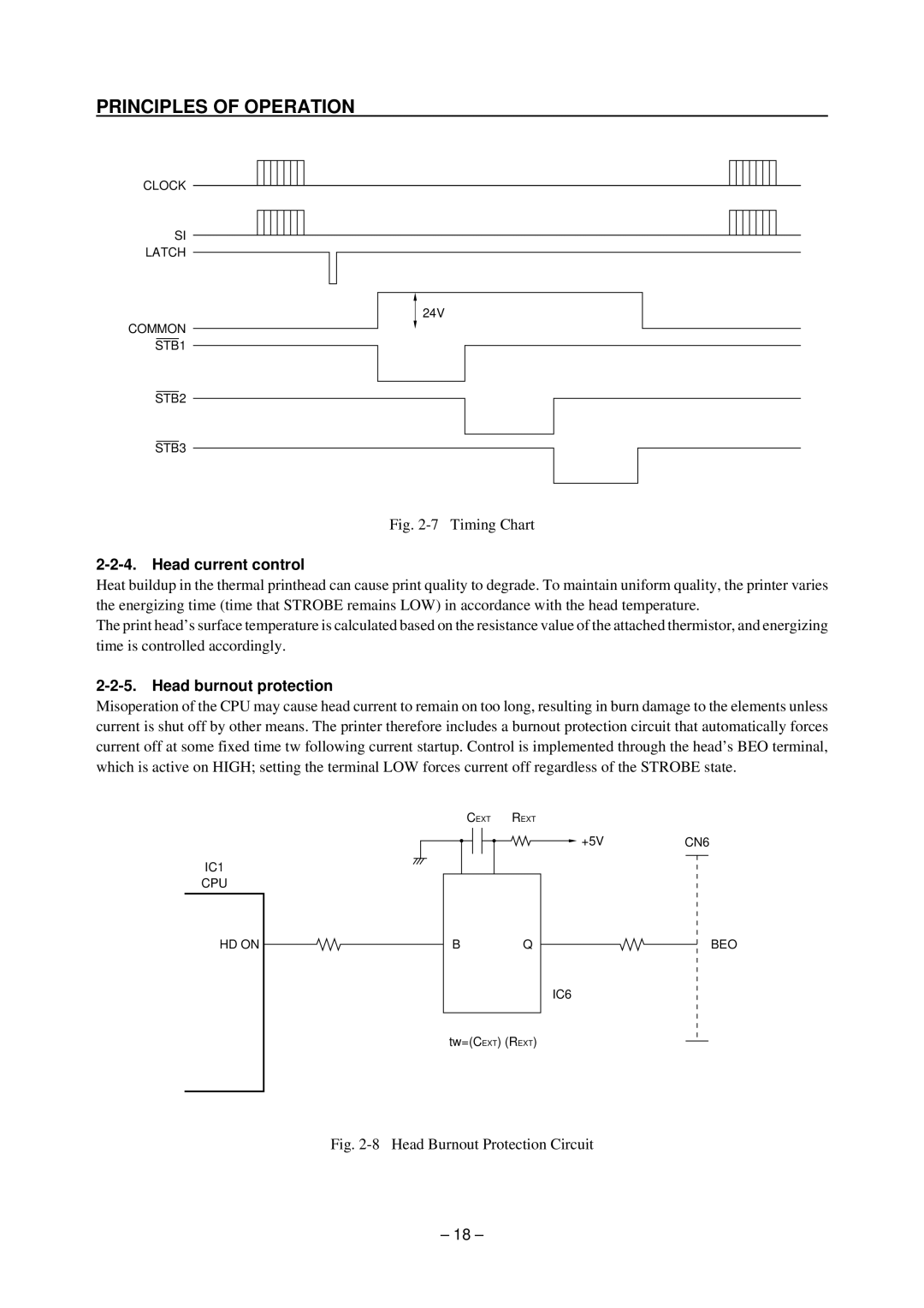
Fig. 2-7 Timing Chart
Heat buildup in the thermal printhead can cause print quality to degrade. To maintain uniform quality, the printer varies the energizing time (time that STROBE remains LOW) in accordance with the head temperature.
The print head’s surface temperature is calculated based on the resistance value of the attached thermistor, and energizing time is controlled accordingly.
Misoperation of the CPU may cause head current to remain on too long, resulting in burn damage to the elements unless current is shut off by other means. The printer therefore includes a burnout protection circuit that automatically forces current off at some fixed time tw following current startup. Control is implemented through the head’s BEO terminal, which is active on HIGH; setting the terminal LOW forces current off regardless of the STROBE state.
CEXT
IC1
CPU
REXT
+5V | CN6 |
|
|
HD ON
BQ
BEO
IC6
tw=(CEXT) (REXT)
Fig. 2-8 Head Burnout Protection Circuit
– 18 –
