ULTRAFORCE COMMERCIAL GAS WATER HEATER
SUF 120 thru 400 SERVICE HANDBOOK
CONTROLS – GAS VALVE , ORIFICE CHART– SUF300,400,
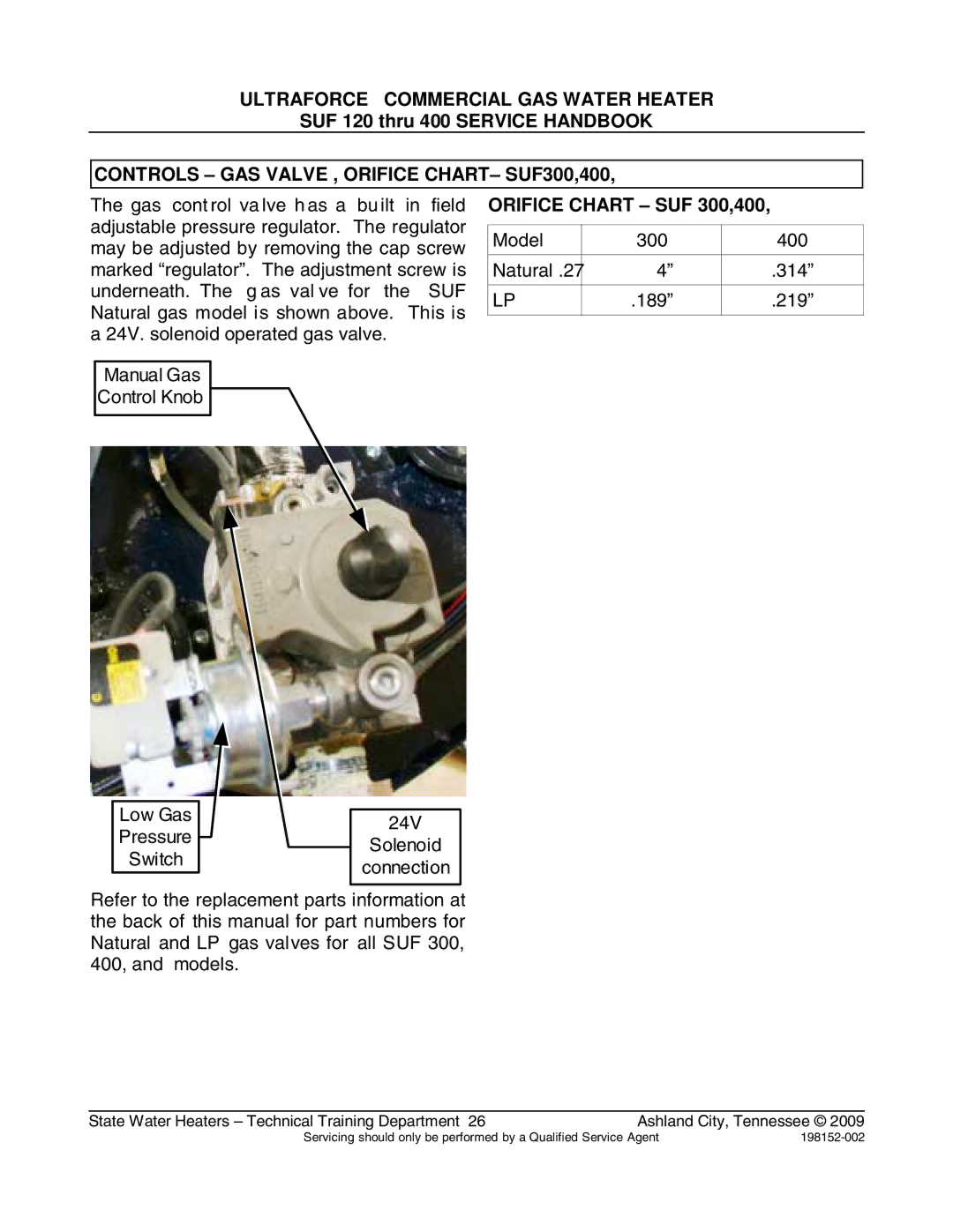
The gas cont rol va lve h as a bu ilt in field adjustable pressure regulator. The regulator may be adjusted by removing the cap screw marked “regulator”. The adjustment screw is underneath. The g as val ve for the SUF Natural gas model is shown above. This is a 24V. solenoid operated gas valve.
Manual Gas
Control Knob
ORIFICE CHART – SUF 300,400,
Model | 300 | 400 |
|
|
|
Natural .27 | 4” | .314” |
|
|
|
LP | .189” | .219” |
|
|
|
Low Gas |
|
|
| ||
24V | |||||
Pressure |
|
|
| ||
|
| Solenoid | |||
|
|
| |||
Switch |
|
|
| ||
|
| connection | |||
|
|
|
| ||
|
|
|
|
| |
Refer to the replacement parts information at the back of this manual for part numbers for Natural and LP gas valves for all SUF 300, 400, and models.
State Water Heaters – Technical Training Department 26 | Ashland City, Tennessee © 2009 |
Servicing should only be performed by a Qualified Service Agent |