Flue Installation for the 705 Model
Air Intake Assembly
The air intake system consists of a field supplied 4 inch diameter stainless steel, Schedule 40 PVC, ABS or CPVC pipe. A maximum 6 feet of
The air intake has a zero clearance to combustibles.
Air Intake Connection
1.Drill 2 small holes at the end of the air intake pipe. 2.Slide the pipe over the air intake terminal.
3.Using a level, ensure the pipe is straight up and down.
4.With self tapping screws, attach the pipe to the air intake terminal.
5.Apply a bead of silicone around the pipe and air intake terminal, ensuring an air tight connection.
12
34
Exhaust Pipe Assembly
Refer to the manufacturer’s installation instructions for the specific exhaust vent system.
Venting Clearances to Combustibles
| Enclosed | Unenclosed |
Vent Size |
|
|
Horizontal & | Horizontal & | |
| Vertical | Vertical |
4" (102 mm) | 4" (102 mm) | 1" (26 mm) |
|
|
|
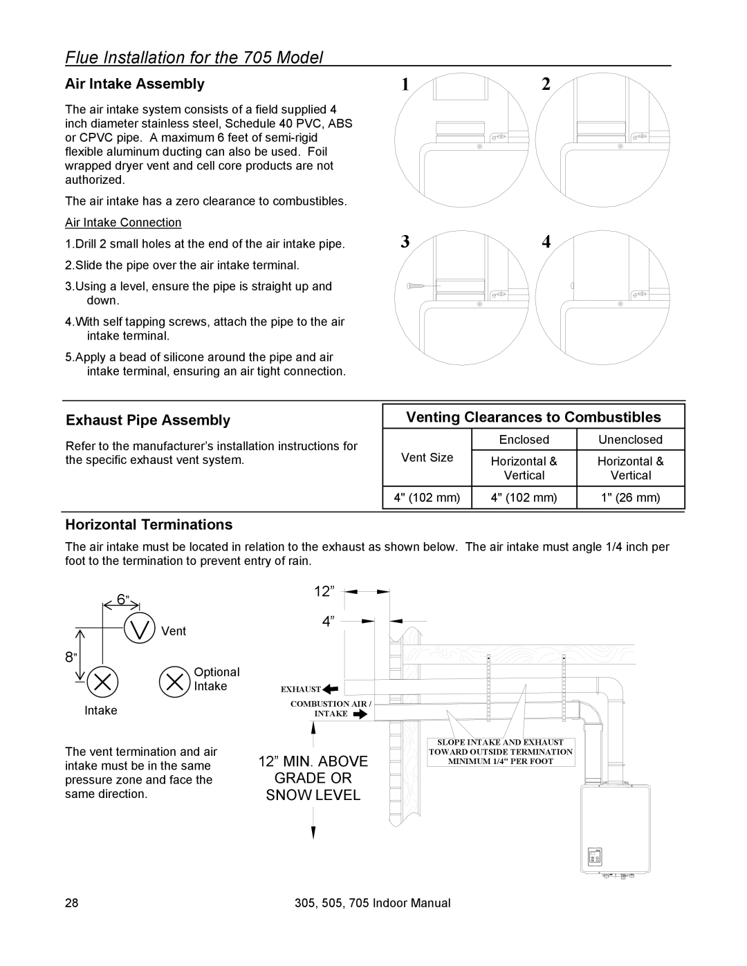
Horizontal Terminations
The air intake must be located in relation to the exhaust as shown below. The air intake must angle 1/4 inch per foot to the termination to prevent entry of rain.
6” | 12” |
| |
Vent | 4” |
| |
8” |
|
Optional |
|
Intake | EXHAUST |
Intake | COMBUSTION AIR / |
INTAKE | |
The vent termination and air | 12” MIN. ABOVE |
intake must be in the same | |
pressure zone and face the | GRADE OR |
same direction. | SNOW LEVEL |
SLOPE INTAKE AND EXHAUST
TOWARD OUTSIDE TERMINATION
MINIMUM 1/4" PER FOOT
|
|
|
|
|
|
|
|
|
|
|
|
|
|
|
|
|
|
|
|
28 | 305, 505, 705 Indoor Manual |
| ||