Temperature Controller Installation
Location
Indoor models have their controller built into the front panel. Additional controllers can also be installed.
•The controller should be out of reach of small children.
•Avoid locations where the controller may become hot (near the oven or radiant heater).
•Avoid locations in direct sunlight. The digital display may be difficult to read in direct sunlight.
•Avoid locations where the temperature controller could be splashed with liquids.
•Do not install in locations where it can be adjusted by the public.
Configurations
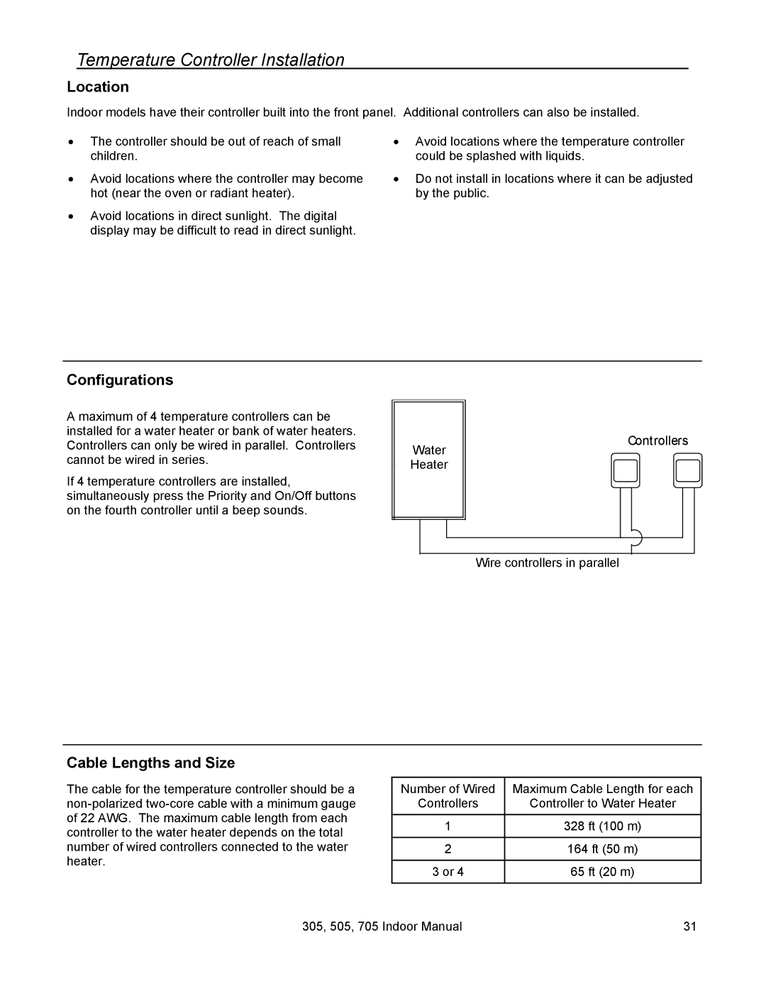
A maximum of 4 temperature controllers can be installed for a water heater or bank of water heaters. Controllers can only be wired in parallel. Controllers
Water
Controllers
cannot be wired in series.
If 4 temperature controllers are installed, simultaneously press the Priority and On/Off buttons on the fourth controller until a beep sounds.
Heater
Wire controllers in parallel
Cable Lengths and Size
The cable for the temperature controller should be a
Number of Wired | Maximum Cable Length for each |
Controllers | Controller to Water Heater |
|
|
1 | 328 ft (100 m) |
|
|
2 | 164 ft (50 m) |
|
|
3 or 4 | 65 ft (20 m) |
|
|
305, 505, 705 Indoor Manual | 31 |