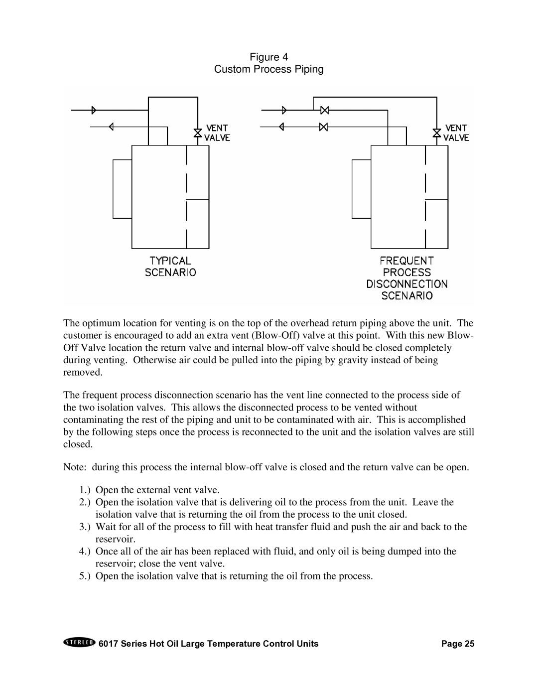
Figure 4
Custom Process Piping
The optimum location for venting is on the top of the overhead return piping above the unit. The customer is encouraged to add an extra vent
The frequent process disconnection scenario has the vent line connected to the process side of the two isolation valves. This allows the disconnected process to be vented without contaminating the rest of the piping and unit to be contaminated with air. This is accomplished by the following steps once the process is reconnected to the unit and the isolation valves are still closed.
Note: during this process the internal
1.) Open the external vent valve.
2.) Open the isolation valve that is delivering oil to the process from the unit. Leave the isolation valve that is returning the oil from the process to the unit closed.
3.) Wait for all of the process to fill with heat transfer fluid and push the air and back to the reservoir.
4.) Once all of the air has been replaced with fluid, and only oil is being dumped into the reservoir; close the vent valve.
5.) Open the isolation valve that is returning the oil from the process.
6017 Series Hot Oil Large Temperature Control Units | Page 25 |