Adjusting the suction tube
4.5. Adjusting the suction tube
To guarantee a
1. The suction tube should be placed in the basic setting
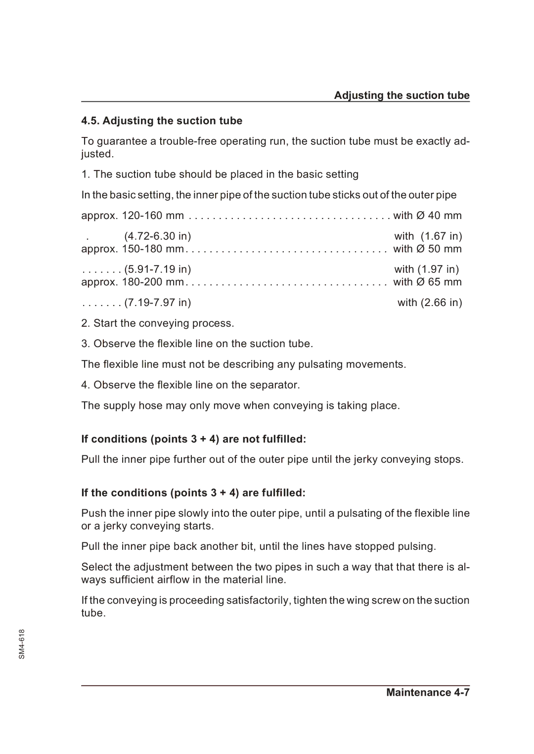
In the basic setting, the inner pipe of the suction tube sticks out of the outer pipe
approx. | with Ø 40 mm | |
. | with (1.67 in) | |
approx. | with Ø 50 mm | |
. . . . . . . | with (1.97 in) | |
approx. | with Ø 65 mm | |
. . . . . . . | with (2.66 in) | |
2.Start the conveying process.
3.Observe the flexible line on the suction tube.
The flexible line must not be describing any pulsating movements. 4. Observe the flexible line on the separator.
The supply hose may only move when conveying is taking place.
If conditions (points 3 + 4) are not fulfilled:
Pull the inner pipe further out of the outer pipe until the jerky conveying stops.
If the conditions (points 3 + 4) are fulfilled:
Push the inner pipe slowly into the outer pipe, until a pulsating of the flexible line or a jerky conveying starts.
Pull the inner pipe back another bit, until the lines have stopped pulsing.
Select the adjustment between the two pipes in such a way that that there is al- ways sufficient airflow in the material line.
If the conveying is proceeding satisfactorily, tighten the wing screw on the suction tube.
