8627 MA, P8627 MA, P8627 BS, 8627 BS specifications
Stovax, a renowned name in the fireplace and wood-burning stove industry, has introduced the P8627 series, which includes models P8627 MA and P8627 BS. These products represent a marriage of innovative technology and traditional design, appealing to both modern and classic aesthetics while ensuring high efficiency and performance.One of the standout features of the P8627 series is its exceptional heat output. These models are engineered to maximize warmth while minimizing fuel consumption, making them an environmentally friendly choice for homeowners. The high-efficiency ratings are complemented by the advanced combustion system that enhances fuel burning, ensuring that more of the wood's energy is converted into heat rather than wasted as smoke.
The P8627 MA model, with its minimalist design and large viewing window, provides an unobstructed view of the fire, creating a warm, inviting ambiance in any living space. It boasts a clean burn technology that significantly reduces emissions, making it an ideal option for eco-conscious consumers. The model's adjustable air control allows users to regulate the burn rate, providing flexibility in how quickly or slowly the fire burns.
On the other hand, the P8627 BS model features a more robust casing, offering added durability while maintaining an elegant appearance. This model also utilizes secondary combustion technology to improve efficiency and reduce particulate emissions. Both models have been tested to comply with stringent environmental standards, ensuring they are safe and efficient for use.
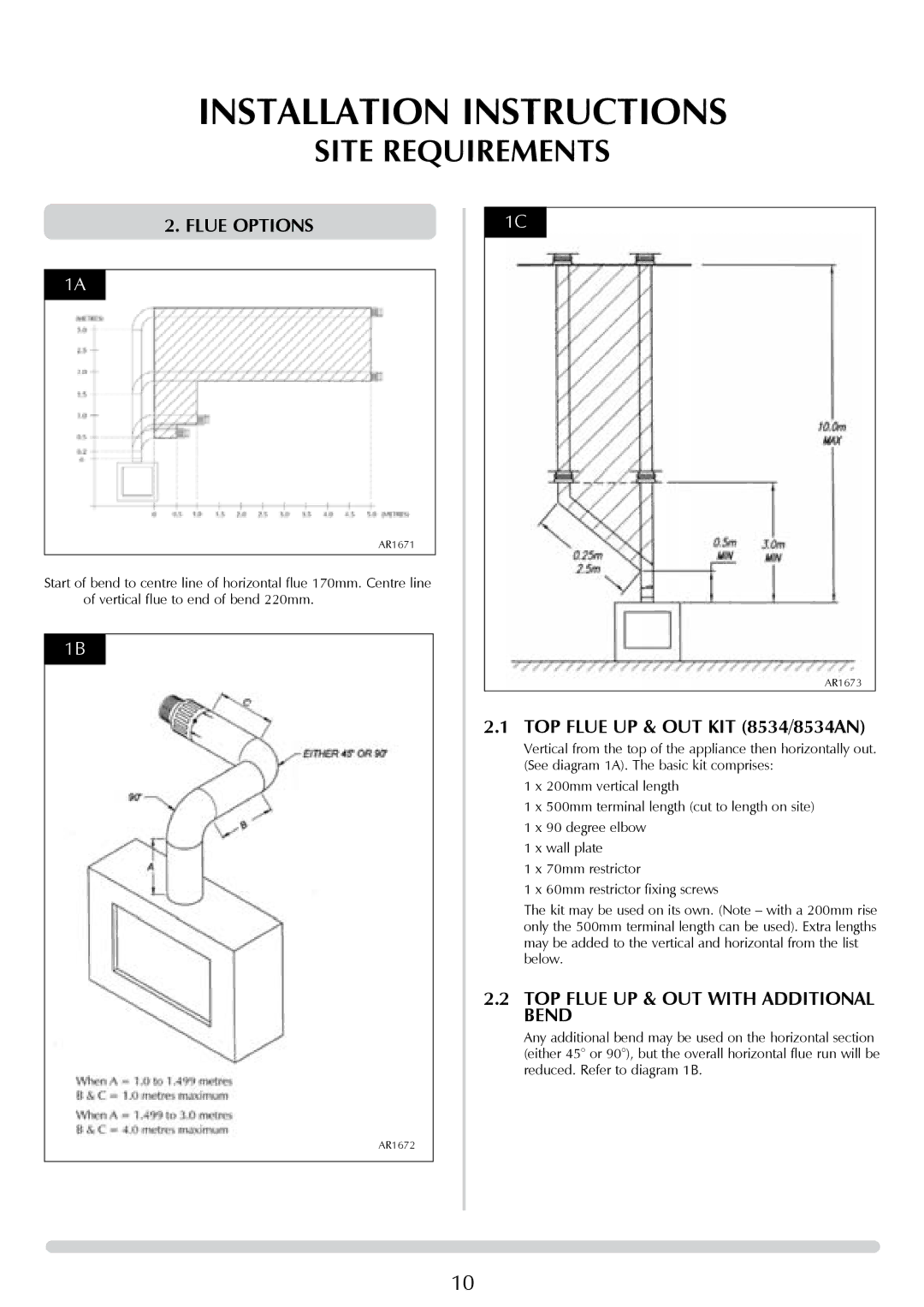
An additional characteristic of the P8627 series is their versatility in installation options. They can be fitted into various settings, whether it be a traditional or contemporary home. With the ability to connect to different flue systems, Stovax ensures that these stoves can accommodate diverse layouts and individual home requirements.
Furthermore, both models are designed with user convenience in mind. The easy-to-use controls, combined with a clean glass design that reduces soot buildup, make maintenance hassle-free. The stylish design options allow homeowners to integrate the stoves seamlessly into their living spaces, enhancing overall aesthetics without compromising functionality.
In summary, the Stovax P8627 MA and P8627 BS models stand out for their efficiency, eco-friendliness, and design versatility. With advanced technologies and user-friendly features, they are an excellent choice for anyone looking to add a reliable and stylish heating solution to their home.

