Cutter Slab Saws
Carr. Fed. Mexico-Puebla KM Tel
Stow Product Support Provided by Multiquip
Wilmington Ave Tel Carson, CA Fax Contact mq@multiquip.com
Fax Contact pmastretta@cipsa.com.mx
Stow Cutter 3 CE SAW Table of Contents
Stow Cutter 3 Slab SAW
Stow Cutter 3 CE SAW Specifications
Cutter 3 Push Cutter 3 Self-Propelled
Stow Cutter 3 CE SAW Engine Specifications
Stow Cutter 3 CE SAW Dimensions
You do not follow these directions
Stow Cutter 3 CE SAW Safety Message Alert Symbols
If you do not follow these directions
You can be Injured if you do not follow these directions
Always wear approved respiratory protection
Always wear approved eye and hearing protection
Stow Cutter 3 CE SAW Rules for Safe Operation
Rules for Safe Operation
General Safety
Diamond Blade Safety
Emergencies
Maintenance Safety
Saw Transportation Safety
Always know the location of the nearest first aid kit
Machine Safety Decals
Stow Cutter 3 Saw Decals
Stow Cutter 3 CE SAW General Information
Stow Cutter 3 CE SAW Major Components
Smoothly
Cannister to gain access to filter element
Stow Cutter 3 CE SAW 13HP Honda Engine Components
Flow of fuel
Fuel Filter Filters fuel for contaminants
Stow Cutter 3 CE SAW 20HP Honda Engine Components
Be shut down
Honda GX390 engine shown
Stow Cutter 3 CE SAW Inspection
Engine Oil Check
Honda 13 HP engine shown
Gasoline Check
Transmission Reservoir
Additionally, when connecting the positive
Battery Self-Propelled models only
Do not overfill the battery
Use only distilled water
Improper under cutting core protection
Pin
Continues, catastrophic failure will occur
Rotation downcuts with the turn of the shaft
Blade Speed
Stow Cutter 3 CE SAW Inspection Blade Placement
Diamond Blades
Inner flange collar
Set the engine ON/OFF switch to the OFF position
Flange
Tight closure on the surface of the blade
Belts and Covers
Guards and Covers Check
Institute Ansi B7.1 and B7.5
Belts Alignment and Tensioning
Following V-belt part numbers listed in Table
Stow Cutter 3 CE SAW Inspection Belts & Water Tank
Water Tank
Adjusting the Blade Height
Stow Cutter 3 CE SAW Inspection Adjustments
Adjusting the Handle Bars
Determining the Cut Depth
Both as an Emergency Engine
Stow Cutter 3 CE SAW Manual START-UP 13HP Honda Engine
HP Engine Manual Start
Engine ON/Off Switch Engine
Throttle Lever
Starter Grip
HP Engine Electric Start
Ensure the wheel clamps are in the Locked position. Figure
Engine Start Switch OFF Position
If the engine must be stopped in an emergency situation
Emergency Stop Procedure
Stow Cutter 3 CE SAW Operation
Traveling During Cutting Push
Neutral Position
Traveling During Cutting Self-Propelled
Place the travel lever in the Neutral position
Engage Position
Cutting
Turn water source on Figure
Extreme heat Restarting After Intervention
Finishing a Cut
Engine components can generate
Stopping the Engine Self-Propelled Models
Stow Cutter 3 CE SAW SHUT-DOWN Procedures
Stopping the Engine Push Model
Saw Blade Removal and Installation
Maintenance
General Cleanliness
Engine oil
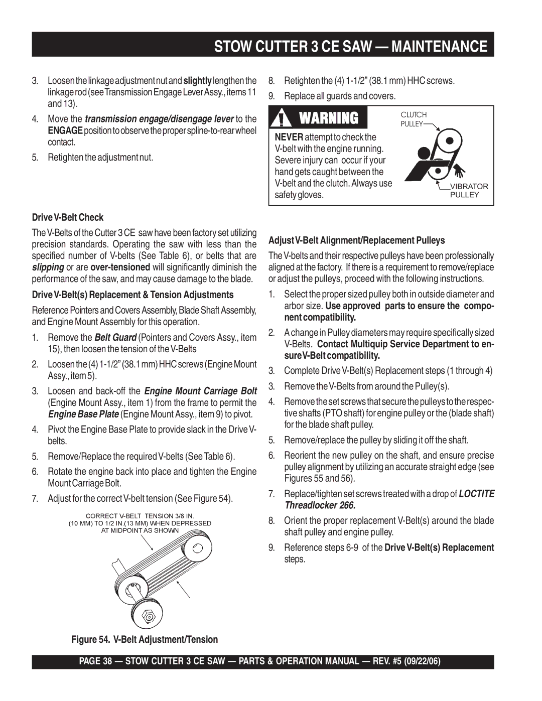
Stow Cutter 3 CE SAW Maintenance
Contact
Retighten the adjustment nut
AdjustV-Belt Alignment/Replacement Pulleys
DriveV-Belt Check
Stow Cutter 3 CE SAW Maintenance
Battery Maintenance
Battery Electrolyte Levels
Decommissioning Saw/Components
Stow Cutter 3 CE SAW 13HP Enginewiring Diagram Recoil Start
Stow Cutter 3 CE SAW 20HP ENG.WIRING Diagram Electric Start
Stow Cutter 3 CE SAW -TROUBLESHOOTING Engine
Stow Cutter 3 CE SAW -TROUBLESHOOTING Engine
Engine Troubleshooting
Stow Cutter 3 CE SAW -TROUBLESHOOTING Blade
Items Found In the Items Number Column
How to read the marks and remarks used in this parts book
Items Found In the Remarks Column
Are subject to change without
Page
Stow Cutter 3 CE SAW Suggested Spare Parts
Description
Stow Cutter 3 CE SAW Name Plate and Decals
Name Plate and Decals
Stow Cutter 3 CE SAW Name Plate and Decals
Under Carriage Assy
WASHER, Flat SAE 3/4
AXLE, Rear & Front
FRAME, Undercarriagee Assy
Bearing Plain
Stow Cutter 3 CE SAW Blade Shaft Assy
Blade Shaft Assy
Stow Cutter 3 CE SAW Blade Shaft Assy
Lifting Bale Assy
BRACE, 13HP Bail
13HP, Lift Bale Assy
20HP, Lift Bail Assy
BRACE, 20HP Bail
Console ASSY. Push Models
Handle Assy
Housing ASSY., Yellow Stow
Console ASSY. Push
WASHER, Lock 3/8 MED
Stow Cutter 3 CE SAW Console ASSY. SELF-PROPELLED
Console ASSY. SELF- Propelled Models
Shift Control Assy
Housing ASSY., Stow Yellow
GRIP, 1 ID
COVER, Rear
13HP Honda Engine Mount Assy
NUT, HEX Finish 1/2-13
Engine Base Assy
20HP Honda Engine Mount Assy
Spacer
Stow Cutter 3 CE SAW 13HP Honda Engine Assy
13HP Honda Engine Assy
Stow Cutter 3 CE SAW 13HP Honda Engine Assy
ENGINE, Honda 13HP, GX390K1QWT2
20HP Honda Engine Assy
PULLEY, Transmission
ENGINE, Honda 20HP GX620TXF2
MOUNT, Idler Spring
Pointers and Covers Assy
Spanner Bushing CSI
Pointer and Covers Assy
Blade Guide Weldment
Pointer
Water System Assy
FITTING, Nipple 1/2MP X 2 Galv
Water System from Console SP
FITTING, Plastic 90 1/2MP X 1/2BARB
Bolt W/NUTS
Blade Guard Assy
Spring TENSION, Guard Blade
Connector 3/8
FITTING, Brass 1/2BARB X 3/4F Grdn
Pipe Strap 3/8
Stow Cutter 3 CE SAW Manual Raise and Lower Assy
Manual Raise and Lower Assy
BEARING, Flange
Jack Screw Assy Blade
Jackscrew
SPACER, Jackscrew
Battery Assy
STRAP, Ground
Bracket Battery
Battery Hold Down KIT
Stow Cutter 3 CE SAW -TRANSMISSION Engage Lever Assy
Transmission Engage Lever Assy
HYD. Transmission Engage Lever Assy
WASHER, Flat SAE 3/8
Hydrostatic Transmission
Stow Cutter 3 CE SAW Hydrostatictransmission Assy
Hydrostatic Transmission Assy
Stow Cutter 3 CE SAW Hydrostatic Drive Assy
Hydrostatic Drive Assy
Stow Cutter 3 CE SAW Hydrostatic Drive Assy
WASHER, Fibre
AIR Cleaner Assy
COLLAR, AIR Cleaner
SEAL, AIR Cleaner Cover
GROMMET, AIR Cleaner
Collar B, AIR Cleaner
Camshaft Assy
ARM, Valve Rocker
SPRING, Weight Return
ROD, Push
LIFTER, Valve
Carburetor Assy
Valve SET, Float
PLATE, Lever Setting
Gasket SET
Float SET
Control Assy
SPRING, Governor
ARM, Governor
ROD, Governor
SPRING, Throttle Return
Crankcase Cover Assy
PIN, Governor Weight
WEIGHT, Governor
HOLDER, Governor Weight
GASKET, Case Cover
Crankshaft Assy
WEIGHT, Balancer
Cylinder Barrel Assy
BOLT, Drain Plug
Switch ASSY., OIL Level
SHAFT, Governor ARM
OIL Seal
Cylinder Head Assy
GASKET, Cylinder Head
GUIDE, Valve OS Optional
CLIP, Valve Guide
COVER, Head
FAN Cover Assy
COVER, FAN *NH1* Black
Switch ASSY., Engine Stop
CLIP, Tube
Shroud
Flywheel Assy
NUT, Special 16MM
FAN, Cooling
Flywheel
Fuel Tank Assy
TANK, Fuel *NH1* Black
RUBBER, Supporter 107MM
JOINT, Fuel Tank
GASKET, Fuel Filler CAP
Ignition Coil Assy
CLIP, Wire Harness
GROMMET, Wire
WIRE, Stop Switch 430MM
Coil ASSY., Ignition
Muffler 1 Assy
PIPE, EX
Muffler
PROTECTOR, Muffler
CAP, Muffler
Piston Assy
Ring SET, Piston 0.75 Nippon
BOLT, Connecting ROD
Ring SET, Piston STD
Piston STD
Recoil Starter Assy
SPRING, Friction
PULLEY, Recoil Starter
RATCHET, Starter
SPRING, Starter Return
Labels Assy
Emblem
LABEL, AIR Cleaner Caution
MARK, AIR Cleaner Sales Point
LABEL, Caution
Honda GX620TXF2 Engine AIR Cleaner Assy
ELEMENT. AIR Cleaner
HOLDER, AIR CLEANER, Upper
HOLDER, AIR CLEANER, Lower
COVER, AIR Cleaner
Honda GX620TXF2 Engine Camshaft Assy
PIN A, Decompression
SHAFT, Rocker ARM
HOLDER, Decompression PIN
PIN B, Decompression
Honda GX620TXF2 Engine Control Assy
Spring Governor
JOINT, ROD
SPRING, Starter
Spring ,THROTTLE Return
Control BOX Assy
CASE, Control
SUB-WIRE Harness Assy
HOLDER, Stop Switch Wire
BRACKET, Case Mounting
Honda GX620TXF2 Engine Crankcase Cover Assy
SCREEN, OIL Filter
SPRING, Relief Valve
COVER, OIL Filter
DIPSTICK, OIL
Honda GX620TXF2 Engine Crankshaft Assy
CRANKSHAFT, T-TYPE
Honda GX620TXF2 Engine Cylinder Barrel Assy
COVER, Breather
COLLAR, Filter Setting
CLAMP, Wire
VALVE, Breather
Honda GX620TXF2 Engine Cylinder Head Assy
CAP, OIL
COVER, Head Filler
GASKET, Head Cover
MANIFOLD,
Honda GX620TXF2 Engine FAN Cover Assy
HOOD, FAN Cover
PLATE, R Side
PLATE, L Side
PLUG, FAN Cover Hole
Honda GX620TXF2 Engine Flywheel Assy
NUT, Flange 20MM
PLATE, Cooling FAN Start
GRID, Screen P.T.O
WASHER, 20MM
Honda GX620TXF2 Engine Ignition Coil Assy
Coil ASSY., L. Ignition
GROMMET, Ignition Wire
Coil ASSY., R. Ignition
Coil ASSY., Charghe
Muffler Assy
Band ASSY. Optional
MUFFLER, High Optional
PIPE, EX. HIGH-L Optional
BOLT, Flange 6X8 Optional
Honda GX620TXF2 Engine Piston and Connecting ROD Assy
Piston & Connecting ROD Assy
Optional
NUT, Connecting ROD
Ring SET, Piston Standard
Piston
Honda GX620TXF2 Engine Fueltank Assy
CAP, Fuel
Fuel Tank
SUPPORT, Fuel Tank
COLLAR, FR. Engine Hanger
Fuel Pump Assy
FILTER, Fuel
Pump ASSY., Fuel
STAY, Fuel Pump
BASE, Clip
Honda GX620TXF2 Engine Carburetor Assy
Screw Washer
GASKET, AIR Cleaner
Screw SET, Drain
CAP, Choke Lever Dust
Starter Motor Assy
Gear SET, Pinion
Cover A. Magnetic Switch
NUT, Washer 6MM
Armature
No Artwork Available
Gasket KIT Assy
061A1ZJ1000
Label Assy
LABEL, Specification GX620
MARK, EMBLEM, GX620
Terms and Conditions of Sale Stow Construction Equipment
Page
Tel 339 Fax 0161 339 Contact kcassell@multiquip.com.uk