E6581429
7.Measures to satisfy the standards
7.1How to cope with the CE standards
7.1.1Measures to satisfy the EMC directive
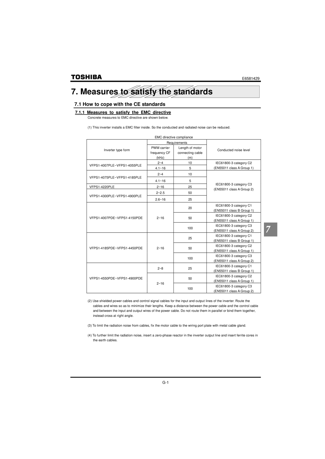
Concrete measures to EMC directive are shown below.
(1)This inverter installs a EMC filter inside. So the conducted and radiated noise can be reduced. EMC directive compliance
| Requirements |
|
|
| |
Inverter type form | PWM carrier | Length of motor | Conducted noise level |
|
|
frequency CF | connecting cable |
|
| ||
|
|
|
| ||
| (kHz) | (m) |
|
|
|
2~4 | 10 |
|
| ||
4.1~16 | 5 | (EN55011 class A Group 1) |
|
| |
|
|
| |||
2~4 | 10 |
|
|
| |
4.1~16 | 5 |
|
| ||
|
|
| |||
2~16 | 25 |
|
| ||
(EN55011 class A Group 2) |
|
| |||
2~2.5 | 50 |
|
| ||
|
|
| |||
2.6~16 | 25 |
|
|
| |
|
|
|
| ||
|
| 20 |
|
| |
|
| (EN55011 class B Group 1) |
|
| |
|
|
|
|
| |
2~16 | 50 |
|
| ||
(EN55011 class A Group 1) |
|
| |||
|
|
|
|
| |
|
| 100 |
| 7 | |
|
| (EN55011 class A Group 2) |
| ||
|
|
|
| ||
|
|
|
|
| |
|
| 25 |
|
| |
|
|
| |||
|
| (EN55011 class B Group 1) |
|
| |
|
|
|
|
| |
2~16 | 50 |
|
| ||
(EN55011 class A Group 1) |
|
| |||
|
|
|
|
| |
|
| 100 |
|
| |
|
| (EN55011 class A Group 2) |
|
| |
|
|
|
|
| |
| 2~8 | 25 |
|
| |
| (EN55011 class B Group 1) |
|
| ||
|
|
|
|
| |
| 50 |
|
| ||
| (EN55011 class A Group 1) |
|
| ||
| 2~16 |
|
|
| |
| 100 |
|
| ||
|
|
|
| ||
|
| (EN55011 class A Group 2) |
|
| |
|
|
|
|
| |
(2)Use shielded power cables and control signal cables for the input and output lines of the inverter. Route the cables and wires so as to minimize their lengths. Keep a distance between the power cable and the control cable and between the input and output wires of the power cable. Do not route them in parallel or bind them together, instead cross at right angle.
(3)To limit the radiation noise from cables, fix the motor cable to the wiring port plate with metal cable gland.
(4)To further limit the radiation noise, insert a