E6581429
(Continued)
|
|
| Item | Specification |
| |
|
|
|
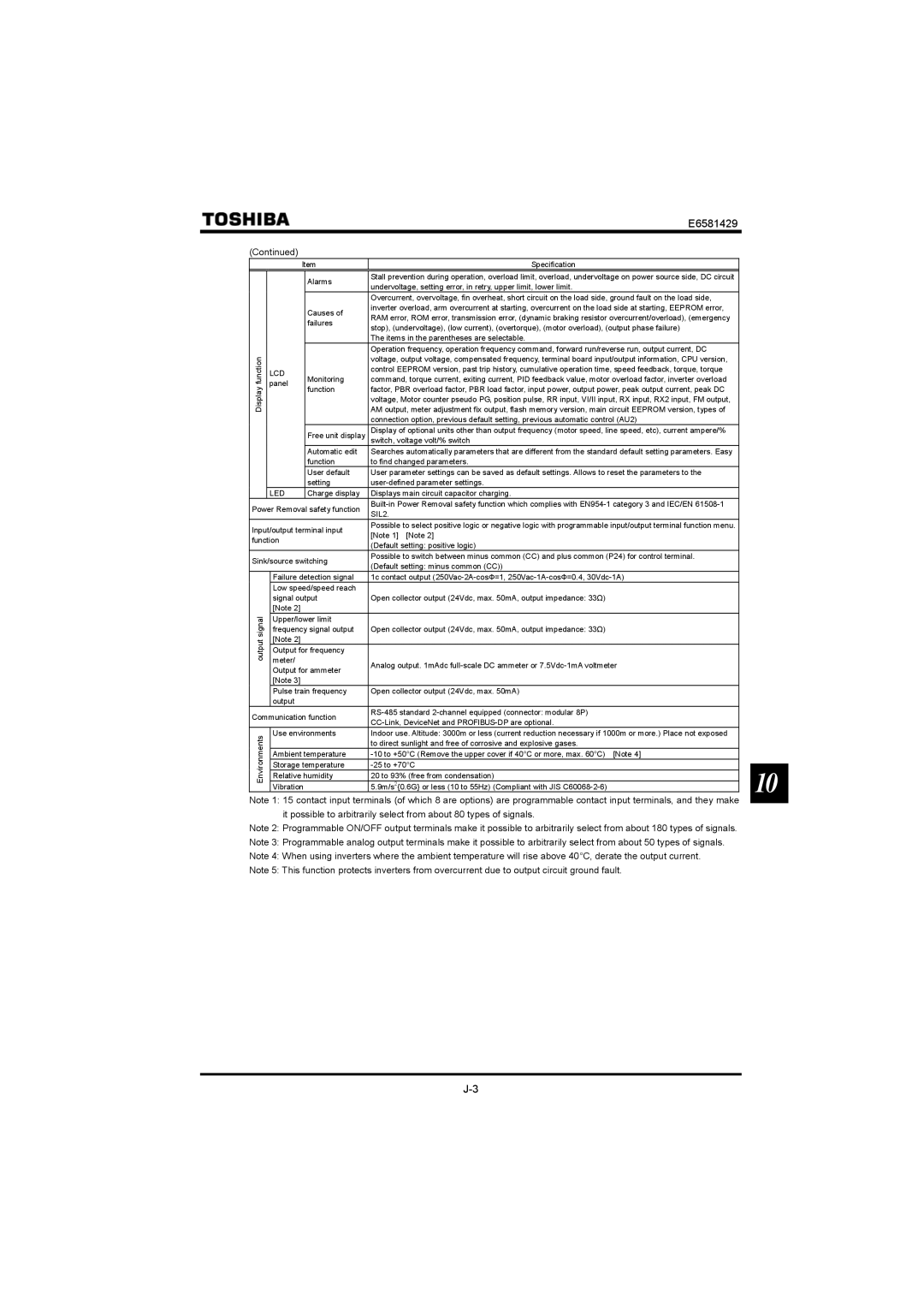
| Alarms | Stall prevention during operation, overload limit, overload, undervoltage on power source side, DC circuit |
|
|
|
|
| undervoltage, setting error, in retry, upper limit, lower limit. |
| |
|
|
|
|
|
| |
|
|
|
|
| Overcurrent, overvoltage, fin overheat, short circuit on the load side, ground fault on the load side, |
|
|
|
|
| Causes of | inverter overload, arm overcurrent at starting, overcurrent on the load side at starting, EEPROM error, |
|
|
|
|
| RAM error, ROM error, transmission error, (dynamic braking resistor overcurrent/overload), (emergency |
| |
|
|
|
| failures |
| |
|
|
|
| stop), (undervoltage), (low current), (overtorque), (motor overload), (output phase failure) |
| |
|
|
|
|
|
| |
|
|
|
|
| The items in the parentheses are selectable. |
|
|
|
|
|
| Operation frequency, operation frequency command, forward run/reverse run, output current, DC |
|
function |
|
|
| Monitoring | voltage, output voltage, compensated frequency, terminal board input/output information, CPU version, |
|
|
|
| command, torque current, exiting current, PID feedback value, motor overload factor, inverter overload |
| ||
| LCD |
|
| control EEPROM version, past trip history, cumulative operation time, speed feedback, torque, torque |
| |
|
|
|
|
| ||
Display | panel |
| function | factor, PBR overload factor, PBR load factor, input power, output power, peak output current, peak DC |
| |
|
|
|
| |||
|
|
|
| AM output, meter adjustment fix output, flash memory version, main circuit EEPROM version, types of |
| |
|
|
|
|
| voltage, Motor counter pseudo PG, position pulse, RR input, VI/II input, RX input, RX2 input, FM output, |
|
|
|
|
|
| connection option, previous default setting, previous automatic control (AU2) |
|
|
|
|
| Free unit display | Display of optional units other than output frequency (motor speed, line speed, etc), current ampere/% |
|
|
|
|
| switch, voltage volt/% switch |
| |
|
|
|
| Automatic edit | Searches automatically parameters that are different from the standard default setting parameters. Easy |
|
|
|
|
| function | to find changed parameters. |
|
|
|
|
| User default | User parameter settings can be saved as default settings. Allows to reset the parameters to the |
|
|
|
|
| setting |
| |
| LED |
| Charge display | Displays main circuit capacitor charging. |
| |
Power Removal safety function |
| |||||
SIL2. |
| |||||
|
|
|
|
|
| |
Input/output terminal input | Possible to select positive logic or negative logic with programmable input/output terminal function menu. |
| ||||
[Note 1] [Note 2] |
| |||||
function |
|
|
| |||
|
| (Default setting: positive logic) |
| |||
|
|
|
|
|
| |
Sink/source switching | Possible to switch between minus common (CC) and plus common (P24) for control terminal. |
| ||||
(Default setting: minus common (CC)) |
| |||||
|
|
|
|
|
| |
|
| Failure detection signal | 1c contact output |
| ||
|
| Low speed/speed reach |
|
| ||
|
| signal output | Open collector output (24Vdc, max. 50mA, output impedance: 33Ω) |
| ||
|
| [Note 2] |
|
|
|
|
signal |
| Upper/lower limit |
|
| ||
| frequency signal output | Open collector output (24Vdc, max. 50mA, output impedance: 33Ω) |
| |||
|
|
| ||||
output |
| [Note 2] |
|
|
|
|
| Output for frequency |
|
| |||
|
|
|
| |||
|
| meter/ |
|
| Analog output. 1mAdc |
|
|
| Output for ammeter |
| |||
|
|
|
| |||
|
| [Note 3] |
|
|
|
|
|
| Pulse train frequency | Open collector output (24Vdc, max. 50mA) |
| ||
|
| output |
|
|
|
|
Communication function |
| |||||
| ||||||
|
|
|
|
|
| |
Environments |
| Use environments | Indoor use. Altitude: 3000m or less (current reduction necessary if 1000m or more.) Place not exposed |
| ||
|
|
|
| to direct sunlight and free of corrosive and explosive gases. |
| |
|
|
|
|
|
| |
|
| Ambient temperature |
| |||
|
| Storage temperature | 10 | |||
|
| Relative humidity | 20 to 93% (free from condensation) | |||
|
|
| ||||
|
| Vibration | 5.9m/s2{0.6G} or less (10 to 55Hz) (Compliant with JIS |
| ||
Note 1: 15 contact input terminals (of which 8 are options) are programmable contact input terminals, and they make it possible to arbitrarily select from about 80 types of signals.
Note 2: Programmable ON/OFF output terminals make it possible to arbitrarily select from about 180 types of signals.
Note 3: Programmable analog output terminals make it possible to arbitrarily select from about 50 types of signals.
Note 4: When using inverters where the ambient temperature will rise above 40°C, derate the output current.
Note 5: This function protects inverters from overcurrent due to output circuit ground fault.