E6581429
7.2Measurements to be taken to satisfy the UL/CSA standards
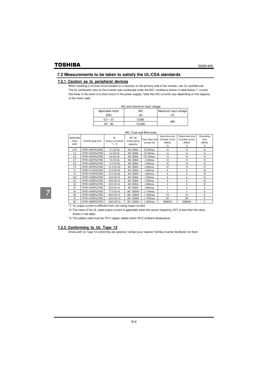
7.2.1Caution as to peripheral devices
When installing a
|
|
|
|
|
| AIC and maximum input voltage |
|
|
| ||||
|
|
|
| Applicable motor | AIC | Maximum input voltage |
|
| |||||
|
|
|
|
|
| (kW) | (A) | (V) |
|
|
| ||
|
|
|
|
| 0.4 ~ 37 | 5,000 | 480 |
|
|
| |||
|
|
|
|
| 45 ~ 90 | 10,000 |
|
|
| ||||
|
|
|
|
|
|
|
|
| |||||
|
|
|
|
|
|
| AIC, Fuse and Wire sizes |
|
|
|
| ||
|
| Applicable |
|
|
| UL | AIC (A) |
| Input wire size | Output wire size | Grounding | ||
|
|
|
|
| Fuse class and | of power circuit | of power circuit | wire | |||||
|
| motor | Inverter type form |
| Output current(A) | (Interrupting | |||||||
|
| (kW) |
|
|
| *1, *2 | capacity) | current (A) | (AWG) | (AWG) | (AWG) | ||
|
|
|
|
|
| *3 | *3 |
| *3 | ||||
|
|
|
|
|
|
|
|
|
| ||||
|
| 0.75 |
| 2.1 (CF=8) | AIC 5000A | CC 6Amax. | 14 | 14 |
| 14 | |||
|
| 1.5 |
| 3.4 (CF=8) | AIC 5000A | CC 6Amax. | 14 | 14 |
| 14 | |||
|
| 2.2 |
| 4.8 (CF=8) | AIC 5000A | CC 12Amax. | 14 | 14 |
| 14 | |||
|
| 3.7 |
| 7.6 (CF=8) | AIC 5000A | J 15Amax. | 12 | 12 |
| 14 | |||
|
| 5.5 |
| 11.0 (CF=8) | AIC 5000A | J 25Amax. | 10 | 10 |
| 12 | |||
|
| 7.5 |
| 14. 0 (CF=8) | AIC 5000A | J 40Amax. | 10 | 10 |
| 12 | |||
|
| 11 |
| 21.0 (CF=8) | AIC 5000A | J 40Amax. | 8 | 8 |
| 10 | |||
|
| 15 |
| 27.0 (CF=8) | AIC 5000A | J 60Amax. | 6 | 6 |
| 10 | |||
|
| 18.5 |
| 34.0 (CF=4) | AIC 5000A | J 70Amax. | 6 | 6 |
| 10 | |||
|
| 22 |
| 40.0 (CF=4) | AIC 5000A | J 70Amax. | 6 | 6 |
| 10 | |||
|
| 30 |
| 52.0 (CF=4) | AIC 5000A | J 80Amax. | 4 | 4 |
| 10 | |||
|
| 37 |
| 65.0 (CF=4) | AIC 5000A | J 90Amax. | 3 | 3 |
| 8 | |||
7 | |||||||||||||
| 45 |
| 77.0 (CF=4) | AIC 10000A | J 110Amax. | 1 | 1 |
| 8 | ||||
| 55 |
| 96.0 (CF=4) | AIC 10000A | J 150Amax. | 1/0 | 1/0 | 6 | |||||
|
| 75 |
| 124.0 (CF=4) | AIC 10000A | J 175Amax. | 3/0 | 3/0 | 6 | ||||
| |||||||||||||
|
| 90 |
| 156.0 (CF=4) | AIC 10000A | J 225Amax. | 250MCM | 250MCM | 2 | ||||
*1: UL output current is different from unit rating output current.
*2: The value of the UL rated output current is applicable when the carrier frequency (CF) is less than the value shown in the table.
*3: The cables used must be 75°C copper cables within 40°C ambient temperature.
7.2.2 Conforming to UL Type 12
Drives with UL Type 12 conformity are optional. Contact your nearest Toshiba inverter distributor for them.