Studer Innotec XPC 2200-48 Control, Display and control parameters, Connection to Remote control

Models: XPC 2200-24

1 23
Download 23 pages 51.43 Kb
Page 11
Image 11
3.6.6Connection to Auxiliary Contact

STUDER Innotec

XP-COMPACT


XPC 1400-12 17-25V/30A, XPC 2200-24 34 – 45V/30A, XPC 2200-48 68 – 90V/20A.

3.6.6Connection to Auxiliary Contact

On these three terminals is a potential free change-over contact. The maximal permitted current and voltage for this is 16A/250Vac. The LED 5 “Contact active” shows the position of them: alight means active and off means non-active. The schematic view of the connections on the front shows the relay in the non-active mode.

3.5.7 Connection to Remote control

The Remote Control RCC 01 is connected in the terminal marked „Remote control“ with a RJ11/8 connector. The Remote Control can be plugged IN or plugged OUT during any operation situation. Push in the connector, without forcing it, until you hear the „click“, now the connector is locked in place. The same applies to the plug in the Remote Control. The length of the cable for Remote Control should not exceed 40m. We deliver it with 20m cable.

3.6.7Connection to Temperature Sensor (Temp.)

The Temperature sensor
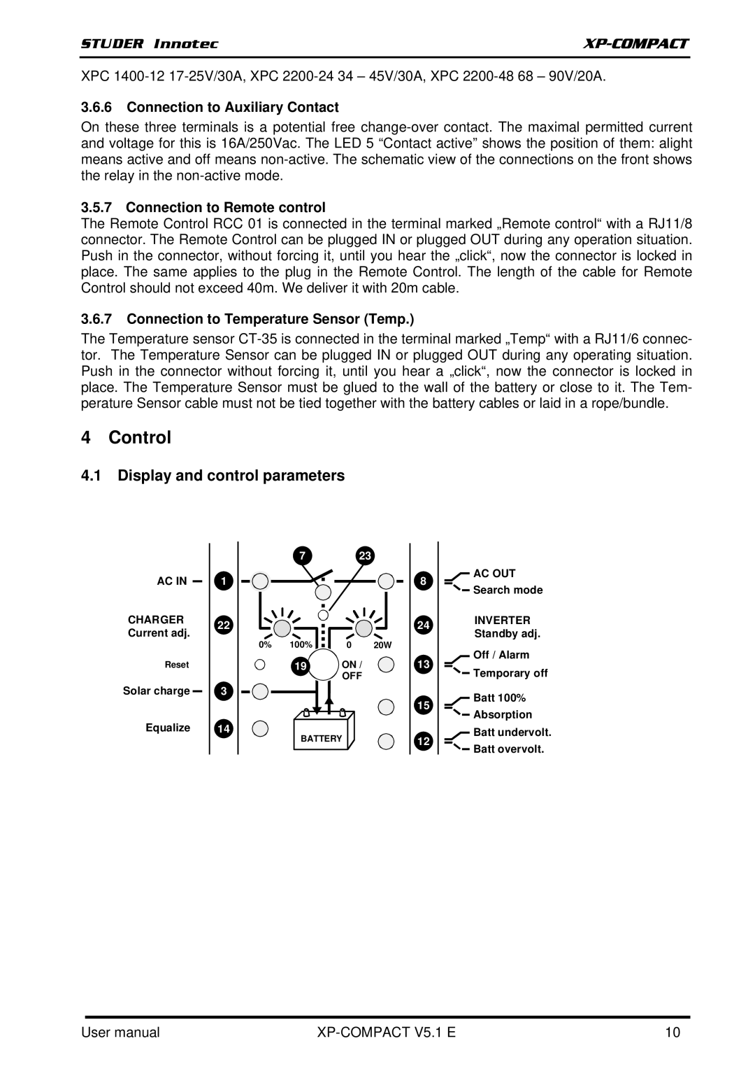
 CT-35 is connected in the terminal marked „Temp“ with a RJ11/6 connec- tor. The Temperature Sensor can be plugged IN or plugged OUT during any operating situation. Push in the connector without forcing it, until you hear a „click“, now the connector is locked in place. The Temperature Sensor must be glued to the wall of the battery or close to it. The Tem- perature Sensor cable must not be tied together with the battery cables or laid in a rope/bundle.

4 Control

4.1Display and control parameters

AC IN

CHARGER Current adj.

Reset

Solar charge

Equalize

1

22

3

14

7 23

0% 100% 3.5.7 Connection to Remote control 0 20W

19ON /

OFF

BATTERY

8

24

13

15

12

3.6.7Connection to Temperature Sensor (Temp.)AC OUT 4 Control Search mode

INVERTER

Standby adj.

4.1Display and control parametersOff / Alarm Manual background Temporary off

Manual backgroundBatt 100%

Absorption

Manual backgroundBatt undervolt. Manual background Batt overvolt.

User manual

XP-COMPACT V5.1 E

10

Page 11
Image 11
Studer Innotec XPC 2200-48 Control, Display and control parameters, Connection to Auxiliary Contact, STUDER Innotec