STUDER Innotec | |
|
|
6.4.3Example
6.4.3.1 Auxiliary Contact as generator starter
When in the programming of the Auxiliary Contact, the Battery Capacity (LED
If you have to start an emergency
6.4.3.2 Auxiliary Contact as Twilight Switch (With solar charger option)
The Auxiliary Contact of the
6.4.3.3 Second priority cut-off
The Auxiliary Contact can use to
6.5Disabling some of the XP-COMPACT functions
Each different function charger, inverter and transfer can be disabled. This is useful for specific applications witch required to disable some of these tree functions.
If you press the buttons (19 and 20) more than 2 seconds, you can have the access to the different possibilities shown in the following diagram.
In programming mode the display show only the different types of program with the three DEL 2,7 and 9 to each functions. To change the type of programming press shortly the button 20 until your reach to the right function use according table below. After 10 seconds the
In user mode, the disabled functions are displayed by blinking LED. So you can see in witch mode is disabled.
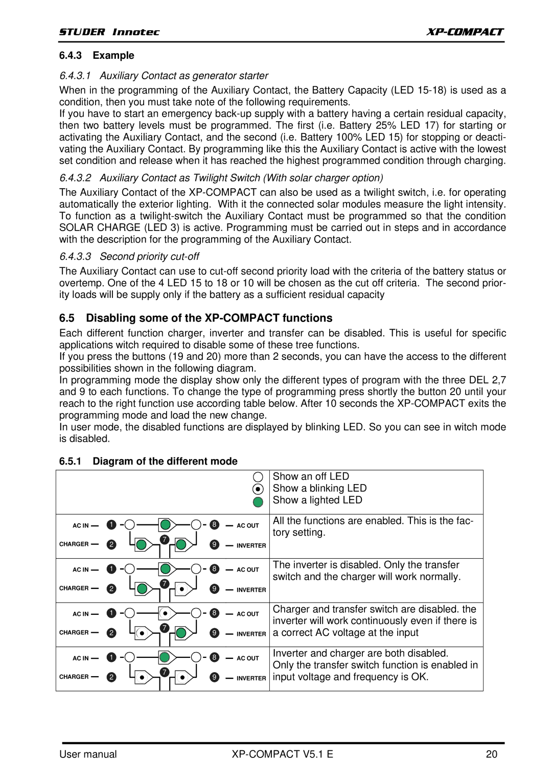
6.5.1Diagram of the different mode
|
|
|
|
|
|
|
|
| Show an off LED |
|
|
|
|
|
|
|
|
| Show a blinking LED |
|
|
|
|
|
|
|
|
| Show a lighted LED |
|
|
|
|
|
|
|
|
|
|
AC IN |
| 1 |
| 8 |
|
|
| AC OUT | All the functions are enabled. This is the fac- |
| 7 |
|
|
| tory setting. | ||||
|
|
|
|
|
|
|
| ||
CHARGER |
| 2 | 9 |
|
|
| INVERTER |
| |
|
|
|
|
|
| ||||
|
|
|
|
|
|
|
|
|
|
AC IN |
| 1 |
| 8 |
|
|
| AC OUT | The inverter is disabled. Only the transfer |
| 7 |
|
|
| switch and the charger will work normally. | ||||
|
|
|
|
|
|
|
| ||
CHARGER |
| 2 | 9 |
|
|
| INVERTER |
| |
|
|
|
|
|
| ||||
|
|
|
|
|
|
|
|
|
|
AC IN |
| 1 |
| 8 |
|
|
| AC OUT | Charger and transfer switch are disabled. the |
| 7 |
|
|
| inverter will work continuously even if there is | ||||
|
|
|
|
|
|
|
| ||
CHARGER |
| 2 | 9 |
|
|
| INVERTER | a correct AC voltage at the input | |
|
|
|
|
| |||||
|
|
|
|
|
|
|
|
|
|
AC IN |
| 1 |
| 8 |
|
|
| AC OUT | Inverter and charger are both disabled. |
| 7 |
|
|
| Only the transfer switch function is enabled in | ||||
|
|
|
|
|
|
|
| ||
CHARGER |
| 2 | 9 |
|
|
| INVERTER | input voltage and frequency is OK. | |
|
|
|
|
| |||||
|
|
|
|
|
|
|
|
|
|
User manual |
| 20 |