STUDER Innotec | |
|
|
2 Introduction
The
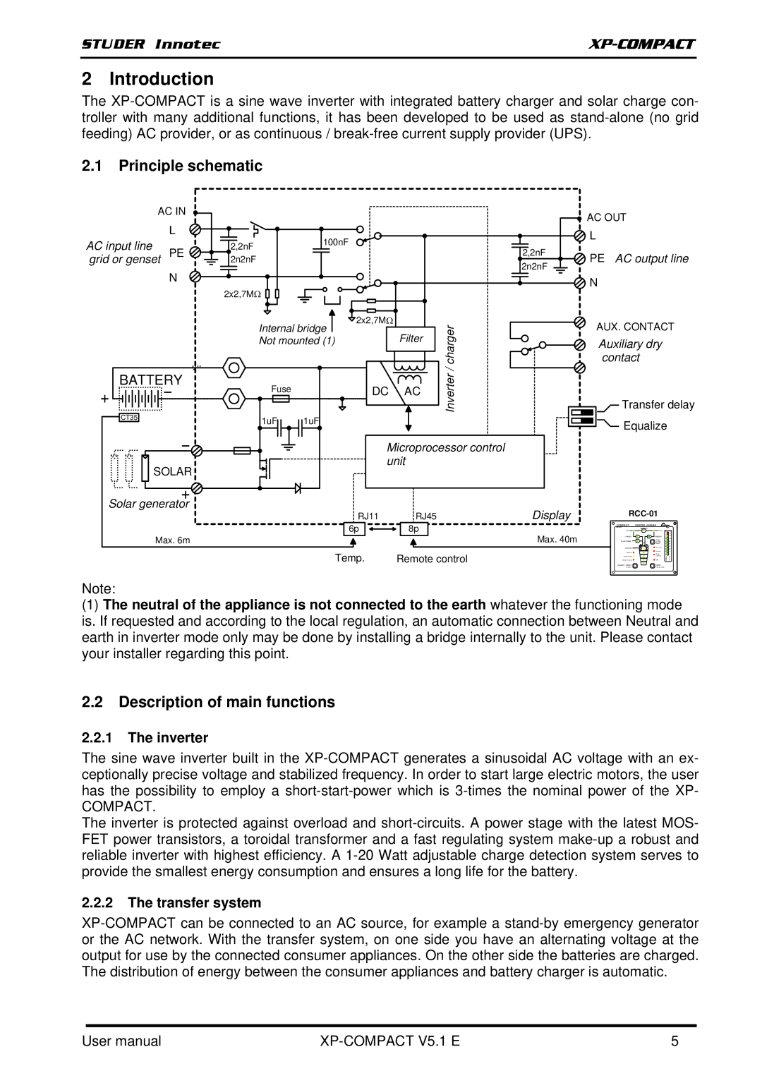
2.1Principle schematic
AC IN
| L |
| 100nF |
|
|
|
AC input line | PE | 2,2nF |
|
|
| |
grid or genset | 2n2nF |
|
|
|
| |
| N |
|
|
|
|
|
|
| 2x2,7MΩ |
|
|
|
|
|
| Internal bridge | 2x2,7MΩ |
| r | |
|
|
|
| |||
|
| Not mounted (1) |
| Filter | eg | |
|
|
|
|
|
| ar |
|
|
|
|
|
| hc |
BATTERY | Fuse |
| DC | AC | e/rt | |
|
|
| erv | |||
|
|
|
|
|
| |
CT35 |
|
|
|
|
| nI |
| 1uF | 1uF |
|
|
| |
|
|
|
|
| ||
Microprocessor control unit
SOLAR
Solar generator
RJ11 | RJ45 |
6p | 8p |
Max. 6m |
|
Temp. | Remote control |
![]() AC OUT
AC OUT
![]() L
L
2,2nF | PE | AC output line | |
2n2nF | |||
|
|
![]() N
N
AUX. CONTACT
Auxiliary dry contact
Transfer delay
Equalize
Display |
|
|
|
| |
| COMPACT | INVERTER - CHARGER |
|
| |
|
| TRANSFER |
|
| |
|
| AC IN | AC OUT | A | % |
Max. 40m |
|
|
|
| 160 |
| CHARGER | (Select) | 50 | 60 | |
|
| INVERTER |
| 130 | |
|
|
| RESET | 70 | 100 |
| SOLAR CHARGE | ALARM | 60 | 80 | |
|
| EQUALIZE | Over Temp. | 40 | 40 |
|
|
| 30 | 20 | |
|
| Program | Overload | 20 | 10 |
|
|
| Battery | 10 | 5 |
| Contact active | Low/High | regrah C | retrevnI | |
| Contact manual | OFF | |||
| AUXILIARY | CONTACT | ON/OFF |
|
|
|
| (Program) | (Change status) |
|
|
Note:
(1)The neutral of the appliance is not connected to the earth whatever the functioning mode is. If requested and according to the local regulation, an automatic connection between Neutral and earth in inverter mode only may be done by installing a bridge internally to the unit. Please contact your installer regarding this point.
2.2Description of main functions
2.2.1The inverter
The sine wave inverter built in the
COMPACT.
The inverter is protected against overload and
2.2.2The transfer system
User manual |
| 5 |
