STUDER Innotec |
|
| |||
|
|
|
|
| |
|
| 20 |
| RESET | |
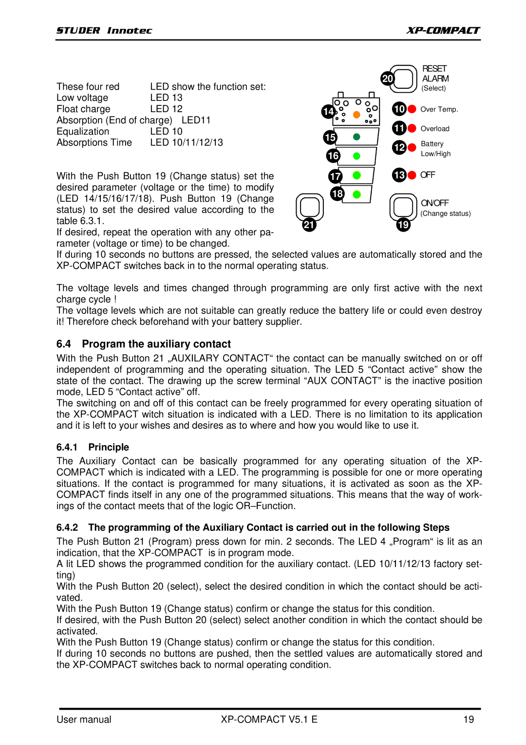
These four red | LED show the function set: |
| ALARM | ||
|
| (Select) | |||
Low voltage | LED 13 |
|
| Over Temp. | |
Float charge | LED 12 | 14 | 10 | ||
Absorption (End of charge) LED11 |
| 11 | Overload | ||
Equalization | LED 10 | 15 | |||
Absorptions Time | LED 10/11/12/13 | 12 | Battery | ||
| |||||
|
| 16 | Low/High | ||
|
|
| |||
With the Push Button 19 (Change status) set the | 17 | 13 | OFF | ||
desired parameter (voltage or the time) to modify | 18 |
|
| ||
(LED 14/15/16/17/18). Push Button 19 (Change |
| ON/OFF | |||
|
| ||||
status) to set the desired value according to the |
|
| |||
|
| (Change status) | |||
table 6.3.1. |
| 21 | 19 | ||
If desired, repeat the operation with any other pa- | |||||
|
|
| |||
rameter (voltage or time) to be changed.
If during 10 seconds no buttons are pressed, the selected values are automatically stored and the
The voltage levels and times changed through programming are only first active with the next charge cycle !
The voltage levels which are not suitable can greatly reduce the battery life or could even destroy it! Therefore check beforehand with your battery supplier.
6.4Program the auxiliary contact
With the Push Button 21 „AUXILARY CONTACT“ the contact can be manually switched on or off independent of programming and the operating situation. The LED 5 “Contact active” show the state of the contact. The drawing up the screw terminal “AUX CONTACT” is the inactive position mode, LED 5 “Contact active” off.
The switching on and off of this contact can be freely programmed for every operating situation of the
6.4.1Principle
The Auxiliary Contact can be basically programmed for any operating situation of the XP- COMPACT which is indicated with a LED. The programming is possible for one or more operating situations. If the contact is programmed for many situations, it is activated as soon as the XP- COMPACT finds itself in any one of the programmed situations. This means that the way of work- ings of the contact meets that of the logic
6.4.2The programming of the Auxiliary Contact is carried out in the following Steps
The Push Button 21 (Program) press down for min. 2 seconds. The LED 4 „Program“ is lit as an indication, that the
A lit LED shows the programmed condition for the auxiliary contact. (LED 10/11/12/13 factory set- ting)
With the Push Button 20 (select), select the desired condition in which the contact should be acti- vated.
With the Push Button 19 (Change status) confirm or change the status for this condition.
If desired, with the Push Button 20 (select) select another condition in which the contact should be activated.
With the Push Button 19 (Change status) confirm or change the status for this condition.
If during 10 seconds no buttons are pushed, then the settled values are automatically stored and the
User manual |
| 19 |