| STUDER Innotec |
|
| ||
|
|
|
|
|
|
|
|
|
|
|
|
|
|
|
| wiring of the installation |
|
|
|
|
|
|
|
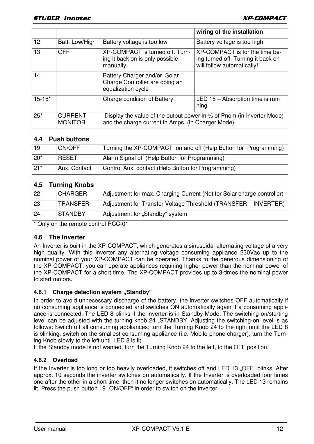
| 12 | Batt. Low/High | Battery voltage is too low | Battery voltage is too high |
|
|
|
|
|
|
|
| 13 | OFF |
| ||
|
|
| ing it back on is only possible | ing turned off. Turning it back on |
|
|
|
| manually. | will follow automatically! |
|
|
|
|
|
|
|
| 14 |
| Battery Charger and/or Solar |
|
|
|
|
| Charge Controller are doing an |
|
|
|
|
| equalization cycle |
|
|
|
|
|
|
|
|
|
| Charge condition of Battery | LED 15 – Absorption time is run- |
| |
|
|
|
| ning |
|
|
|
|
|
|
|
| 25* | CURRENT | Display the value of the output power in % of Pnom (in Inverter Mode) |
| |
|
| MONITOR | and the charge current in Amps. (in Charger Mode) |
| |
|
|
|
|
|
|
4.4Push buttons
19 | ON/OFF | Turning the |
|
|
|
20* | RESET | Alarm Signal off (Help Button for Programming) |
|
|
|
21* | Aux. Contact | Control Aux. contact (Help Button for Programming) |
|
|
|
4.5 | Turning Knobs |
| |
22 |
| CHARGER | Adjustment for max. Charging Current (Not for Solar charge controller) |
|
|
|
|
23 |
| TRANSFER | Adjustment for Transfer Voltage Threshold (TRANSFER – INVERTER) |
|
|
|
|
24 |
| STANDBY | Adjustment for „Standby“ system |
|
|
|
|
* Only on the remote control
4.6The Inverter
An Inverter is built in the
4.6.1Charge detection system „Standby“
In order to avoid unnecessary discharge of the battery, the inverter switches OFF automatically if no consuming appliance is connected and switches ON automatically again if a consuming appli- ance is connected. The LED 8 blinks if the inverter is in
If the Standby mode is not wanted, turn the Turning Knob 24 to the left, to the OFF position.
4.6.2Overload
If the Inverter is too long or too heavily overloaded, it switches off and LED 13 „OFF“ blinks. After approx. 10 seconds the inverter switches on automatically. If the Inverter is overloaded four times one after the other in a short time, then it no longer switches on automatically. The LED 13 remains lit. Press the push button 19 „ON/OFF“ in order to switch on the inverter.
User manual |
| 12 |
