6-3-6 STARTING PULLEY and FLYWHEEL (magneto)
Remove | 3 piecesmountingboltstodetachstarting |
|
|
| ||
pulley from flywheel. |
|
|
|
|
| |
Remove flywheel from crankshaft. |
|
|
| |||
Insertasocketwrench | or boxwrenchintoan | 18mm |
|
| ||
nut,and | give thewrenchasharpblowwithasoft |
|
|
| ||
hammer. Remove nut and spring washer. |
|
|
| |||
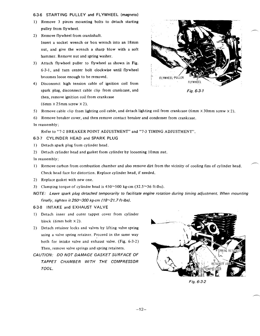
AttachflywheelpullertoflywheelasshowninFig. |
|
|
| |||
|
|
| ||||
becomes loose enough to be removed. |
|
|
| |||
Disconnecthightensioncable | of ignitioncoilfrom |
|
| |||
disconnectcableclipfromcrankcase,andplug,spark |
|
|
| Fig. |
| |
then, remove ignition coil from crankcase |
|
|
| |||
(6mm X 25mm screw X 2). |
|
|
|
| ||
Remove cable clip from lighting coil cable, and detach lighting coil from crankcase (6mm | X 30mm screw x 2). |
| ||||
Remove breaker cover, and then remove contact breaker and condenser from crankcase. |
|
| ||||
In reassembly ; |
|
|
|
|
| |
Refer to |
|
| ||||
| and SPARKPLUG |
|
|
| ||
1 ) Detachsparkplugfromcylinderhead. |
|
| - | |||
2) Detach cylinder head and gasket from cylinder by loosening lOmm nut. |
| |||||
In reassembly; |
|
|
|
| ||
1 ) Remove carbon from combustion chamber and | also remove dirt from the vicinity of cooling fins of cylinder head. | |||||
Check head face for distortion. Replace cylinder head, if needed. |
|
| ||||
2)Replacegasketwithnew | one. |
|
|
|
| |
3)Clamping torque of cylinder head is
NOTE: Leavespark plug detached temporarily to facilitate engine rotation duringtiming adjustment. When mounting
finally, tighten it 250-300 kg-cm (18-21.7 ft-lbs).
6-3-8 INTAKE and EXHAUST VALVE
Detachinnerandoutertappetcover fromcylinder block (6mm bolt x 2).
Detach retainer locks and valves by Lifting valve spring
using a valvespringretainer.Proceed in thesameway
bothforintake valve andexhaust valve. (Fig.
CA1JTION: DO NOT DAMAGE GASKET SURFACE OF
TAPPET CHAMBER WITH THE COMPRESSOR
TOOL.
Fig.
- 1 2-
