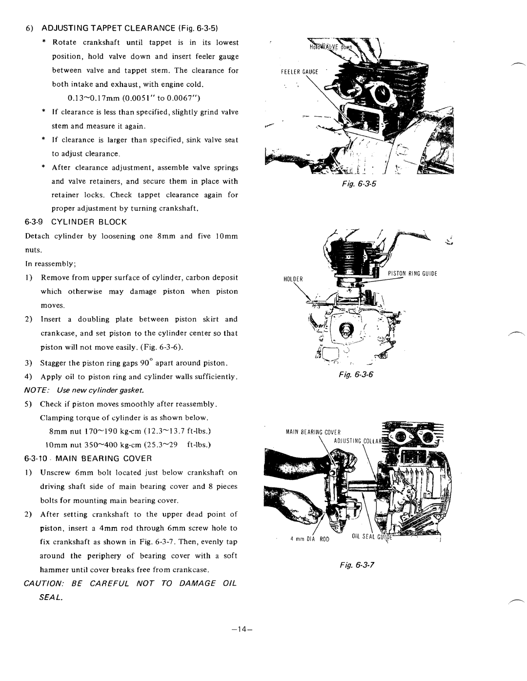
6)ADJUSTING TAPPET CLEARANCE (Fig. 6-3-5)
* Rotatecrankshaftuntiltappetis initslowest
position,hold valve downandinsertfeelergauge between valve andtappetstem.Theclearancefor both intake and exhaust, with engine cold.
*If clearance is less than specified, slightly grind valve stem and measure it again.
*If clearance is largerthanspecified,sink valve seat to adjust clearance.
*Afterclearanceadjustment,assemble valvesprings
and valve retainers,andsecurethem in placewith
retainerlocksChecktappetclearance.again for proper adjustment by turning crankshaft.
6-3-9 CYLINDERBLOCK
Detachcylinderbylooseningone8mmandfivelOmm
nuts.
In reassembly;
Fig.
Remove from upper surfaceof cylinder, carbon deposit
HOLDER
R I N G GUIDE
whichotherwisemaydamagepistonwhenpiston
moves. lnsertadoublingplatebetweenpistonskirtand
crankcase, and set piston to the cylinder center so that piston will not move easily. (Fig.
Stagger the piston ring gaps 90° apart around piston. Apply oil to piston ring and cylinder walls sufficiently.
NOTE: Use new cylinder gasket.
5)Check if pistonmovessmoothlyafterreassembly. Clamping torque of cylinder is as shown below.
8mm nut
6-3-70.MAINBEARING COVER
I ) Unscrew 6mmboltlocated just belowcrankshafton
drivingshaftside of mainbearingcoverand 8 pieces
bolts for mounting main bearing cover.
2)Aftersettingcrankshafttotheupperdeadpointof piston,inserta 4mm rodthrough6mmscrew hole t o fix crankshaft as shown in Fig.
aroundtheperipheryofbearingcoverwithasoft
hammer until cover breaks free from crankcase.
CAUTION: BE CAREFULNOT TO DAMAGE OIL
SEA 1.
\
. 1 ; :~ d
Fig.
MAIN BEARING COVER
Fig.
”1 4-