SERIES3800/S120T
Possible System Memory Allocation & Availability
System Device
Firmware Hub flash memory (System BIOS)
Local APIC
Area Reserved for the chipset
I/O APIC (4 Kbytes)
PCI Enumeration Area 1
PCI Express (256 MB)
PCI Enumeration Area 2 (if needed)
VGA Memory
TSEG
Memory available to OS and other ap- plications
Size
1 MB
4KB
2MB
4KB
256MB
256MB
512MB
16MB
1MB
Physical Memory
Remaining
(4 GB Total System Memory)
3.99
3.99
3.99
3.99
3.76
3.51
3.01
2.85
2.84
2.84
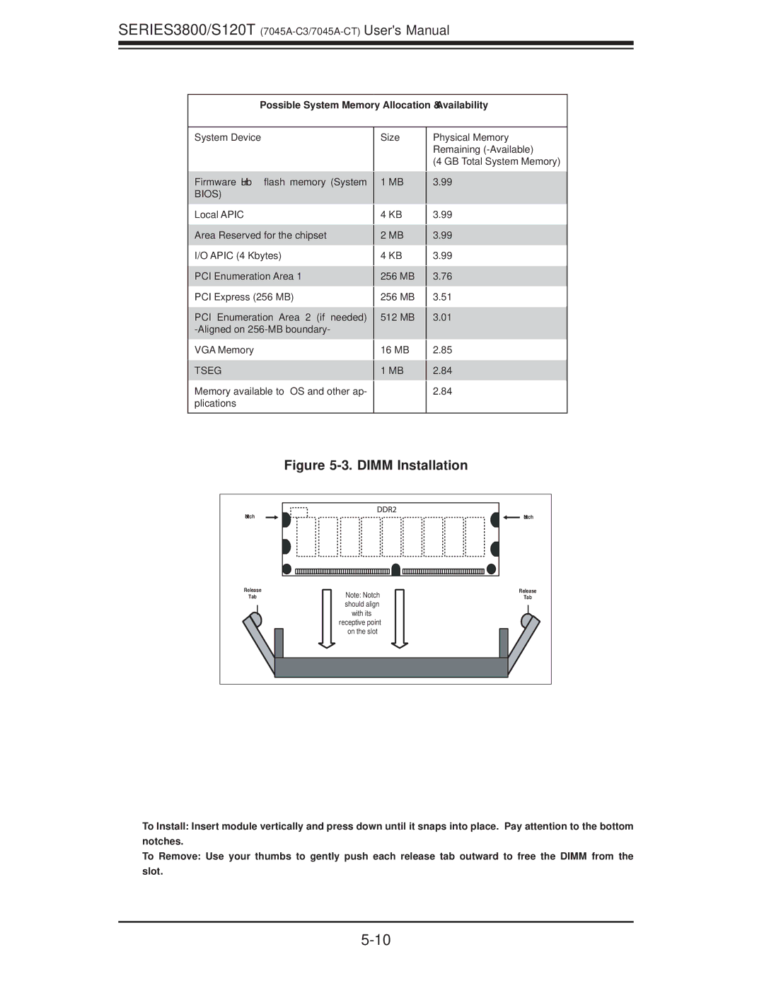
Figure 5-3. DIMM Installation
Notch |
| Notch |
Release | Note: Notch | Release |
Tab | Tab | |
| should align |
|
| with its |
|
| receptive point |
|
| on the slot |
|
To Install: Insert module vertically and press down until it snaps into place. Pay attention to the bottom notches.
To Remove: Use your thumbs to gently push each release tab outward to free the DIMM from the slot.