SERIES3800/S120T
HDD LED
The HDD LED connection is located on pins 13 and 14 of JF1. This LED is used to display all IDE and SATA activity. See the table on the right for pin definitions.
Power On LED
The Power On LED connector is lo- cated on pins 15 and 16 of JF1 (use JLED for a
NMI Button
The
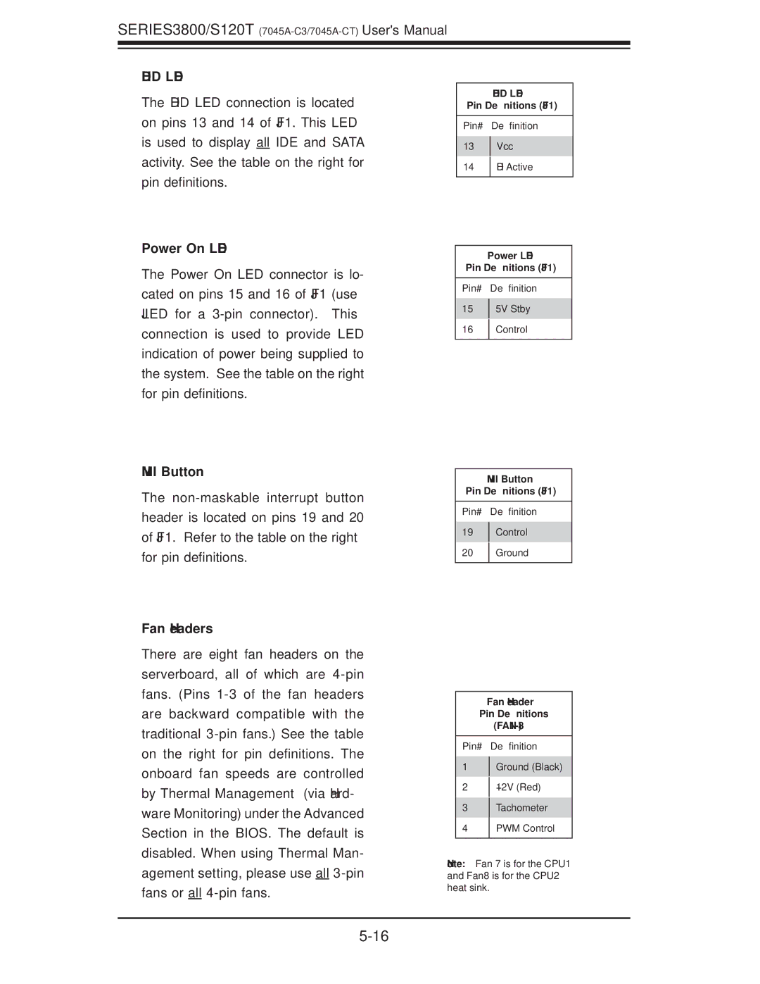
Fan Headers
There are eight fan headers on the serverboard, all of which are
HDD LED
Pin Definitions (JF1)
Pin# Definition
13Vcc
14HD Active
Power LED
Pin Definitions (JF1)
Pin# Definition
155V Stby
16Control
NMI Button
Pin Definitions (JF1)
Pin# Definition
19Control
20Ground
Fan Header
Pin Definitions
Pin# Definition
1Ground (Black)
2+12V (Red)
3Tachometer
4PWM Control
Note: Fan 7 is for the CPU1 and Fan8 is for the CPU2 heat sink.