SERIES3800/S120T
5-12 Parallel, Floppy, IDE, and SATA Ports
Use the following information to connect the IDE hard disk drive cables.
•A red mark on a wire typically designates the location of pin 1.
•The
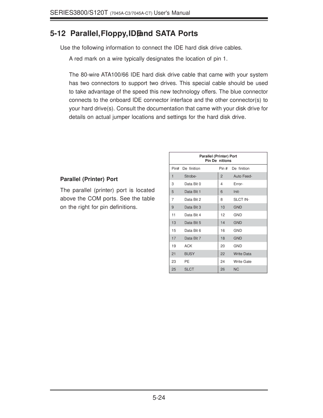
Parallel (Printer) Port
Pin Definitions
Parallel (Printer) Port
The parallel (printer) port is located above the COM ports. See the table on the right for pin definitions.
Pin# Definition
1Strobe-
3Data Bit 0
5Data Bit 1
7Data Bit 2
9Data Bit 3
11Data Bit 4
13Data Bit 5
15Data Bit 6
17Data Bit 7
19ACK
21BUSY
23PE
25SLCT
Pin # Definition
2 Auto Feed-
4 Error-
6 Init-
8SLCT IN-
10GND
12GND
14GND
16GND
18GND
20GND
22Write Data
24Write Gate
26NC