Chapter 5: Advanced Serverboard Setup
Reset Connector
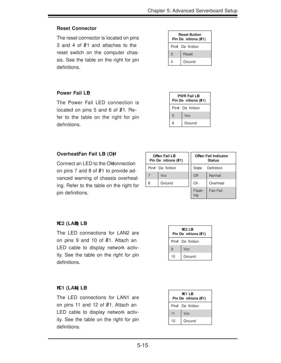
The reset connector is located on pins 3 and 4 of JF1 and attaches to the reset switch on the computer chas- sis. See the table on the right for pin definitions.
Power Fail LED
The Power Fail LED connection is located on pins 5 and 6 of JF1. Re- fer to the table on the right for pin definitions.
Reset Button
Pin Definitions (JF1)
Pin# Definition
3Reset
4Ground
PWR Fail LED
Pin Definitions (JF1)
Pin# Definition
5Vcc
6Ground
Overheat/Fan Fail LED (OH)
Connect an LED to the OH connection on pins 7 and 8 of JF1 to provide ad- vanced warning of chassis overheat- ing. Refer to the table on the right for pin definitions.
NIC2 (LAN2) LED
OH/Fan Fail LED
Pin Definitions (JF1)
Pin# Definition
7Vcc
8Ground
OH/Fan Fail Indicator
Status
State Definition
Off | Normal | |
On | Overheat | |
Flash- | Fan Fail | |
ing |
| |
|
|
The LED connections for LAN2 are on pins 9 and 10 of JF1. Attach an LED cable to display network activ- ity. See the table on the right for pin definitions.
NIC1 (LAN1) LED
The LED connections for LAN1 are on pins 11 and 12 of JF1. Attach an LED cable to display network activ- ity. See the table on the right for pin definitions.
NIC2 LED
Pin Definitions (JF1)
Pin# Definition
9Vcc
10Ground
NIC1 LED
Pin Definitions (JF1)
Pin# Definition
11Vcc
12Ground