Chapter 1: Introduction
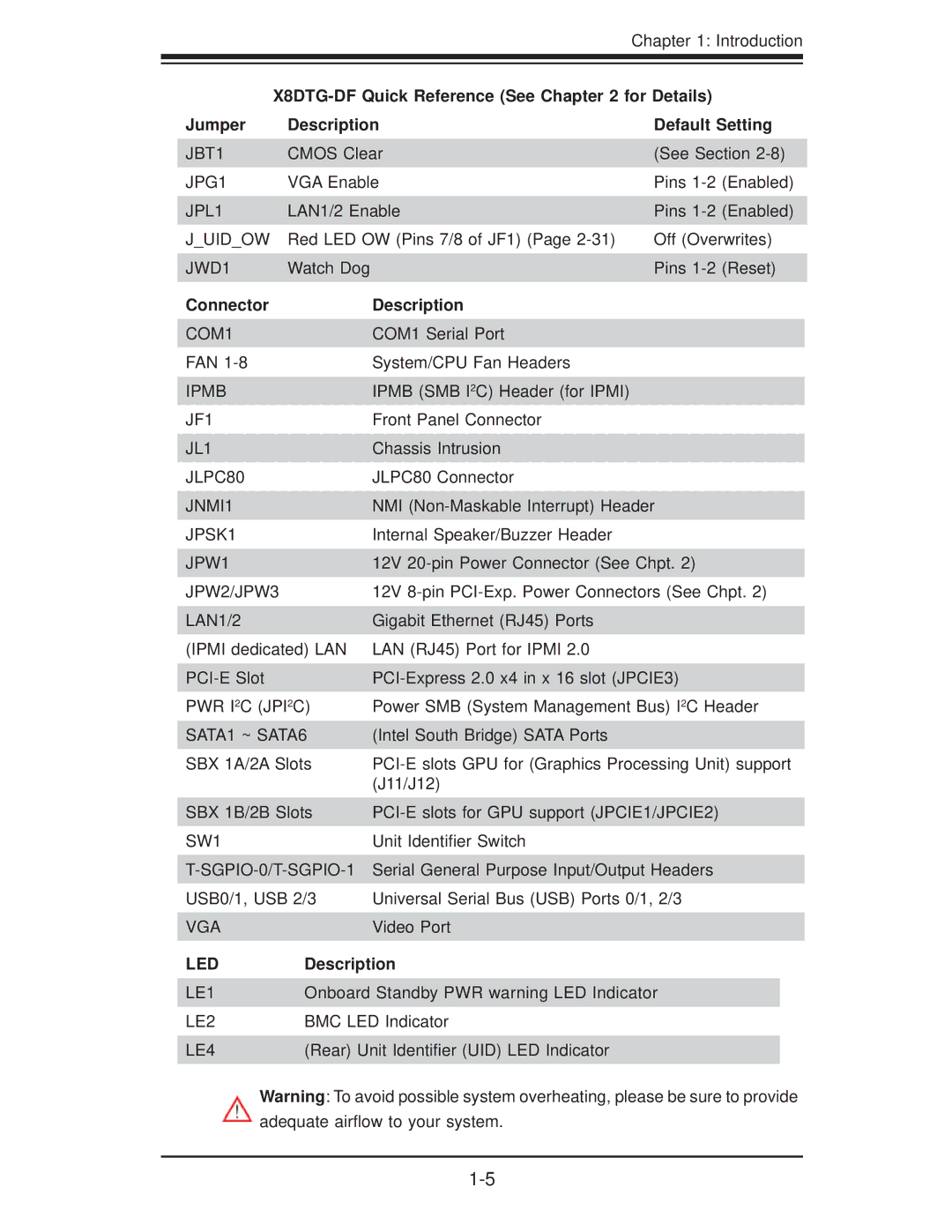
Jumper | Description | Default Setting | |
JBT1 | CMOS Clear | (See Section | |
JPG1 | VGA Enable | Pins | (Enabled) |
JPL1 | LAN1/2 Enable | Pins | (Enabled) |
J_UID_OW | Red LED OW (Pins 7/8 of JF1) (Page | Off (Overwrites) | |
JWD1 | Watch Dog | Pins | (Reset) |
Connector | Description |
COM1 | COM1 Serial Port |
FAN | System/CPU Fan Headers |
IPMB | IPMB (SMB I2C) Header (for IPMI) |
JF1 | Front Panel Connector |
JL1 | Chassis Intrusion |
JLPC80 | JLPC80 Connector |
JNMI1 | NMI |
JPSK1 | Internal Speaker/Buzzer Header |
JPW1 | 12V |
JPW2/JPW3 | 12V |
LAN1/2 | Gigabit Ethernet (RJ45) Ports |
(IPMI dedicated) LAN | LAN (RJ45) Port for IPMI 2.0 |
PWR I2C (JPI2C) | Power SMB (System Management Bus) I2C Header |
SATA1 ~ SATA6 | (Intel South Bridge) SATA Ports |
SBX 1A/2A Slots | |
| (J11/J12) |
SBX 1B/2B Slots | |
SW1 | Unit Identifier Switch |
| Serial General Purpose Input/Output Headers |
USB0/1, USB 2/3 | Universal Serial Bus (USB) Ports 0/1, 2/3 |
VGA | Video Port |
LED | Description |
LE1 | Onboard Standby PWR warning LED Indicator |
LE2 | BMC LED Indicator |
LE4 | (Rear) Unit Identifier (UID) LED Indicator |
Warning: To avoid possible system overheating, please be sure to provide adequate airflow to your system.
