Chapter 2: Installation
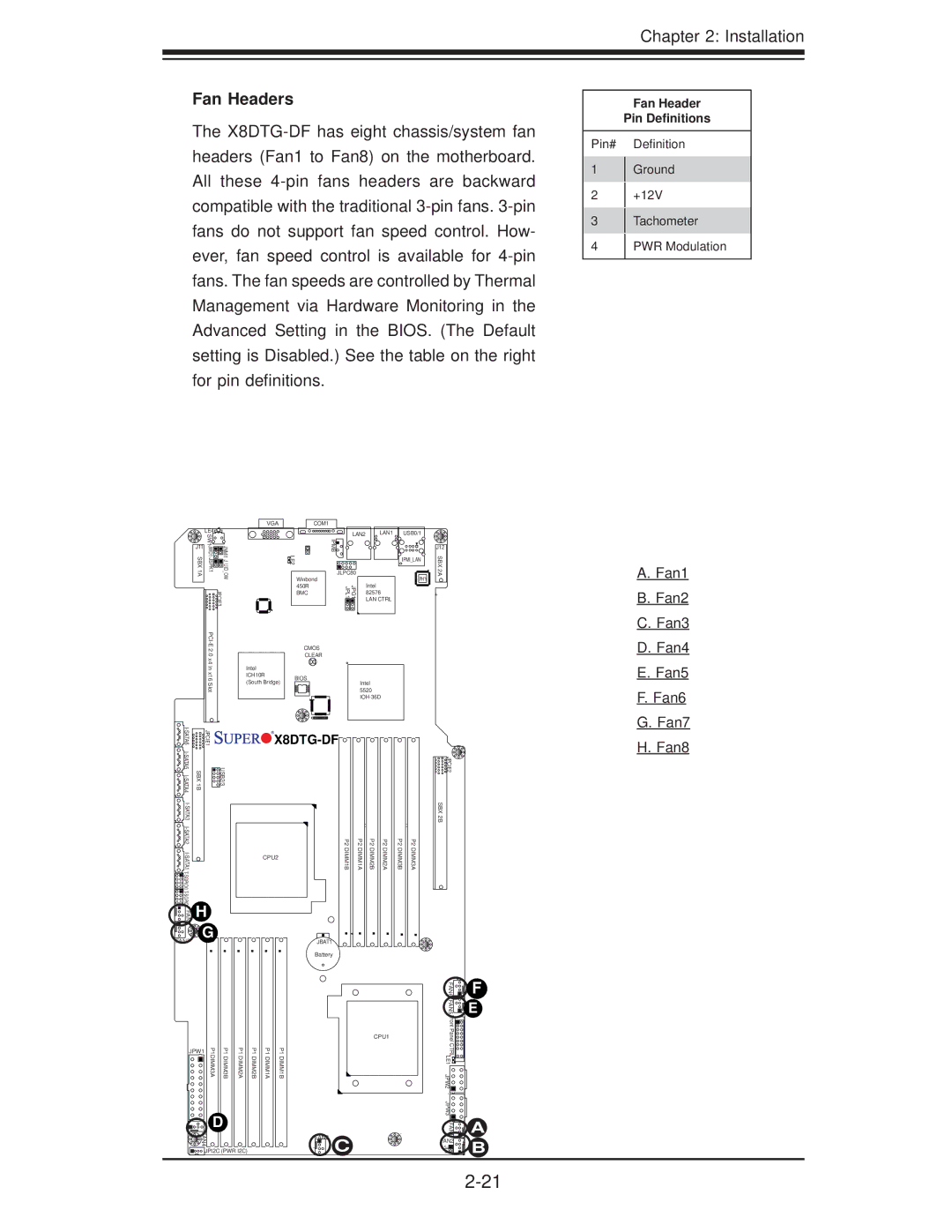
Fan Headers
The
Fan Header
Pin Definitions
Pin# Definition
1Ground
2+12V
3Tachometer
4PWR Modulation
LE4![]()
![]()
![]()
J11 | SW1 |
| |
JWD1 JSPK1 | JNMI1 J_UID_OW | ||
SBX 1A | |||
|
| JPCIE3 | |
|
|
VGA |
| COM1 |
|
|
|
|
|
| LAN2 | LAN1 | USB0/1 |
| |
| LE2 | IPMB |
|
|
| J12 |
|
|
|
| IPMI_LAN | SBX | |
|
|
|
|
|
| |
|
| JLPC80 |
|
| PHY | 2A |
| Winbond |
| Intel |
| ||
| 450R | JPG1 JPL1 |
|
|
| |
| BMC |
| 82576 |
| + | |
|
|
|
| LAN CTRL |
|
|
| CMOS |
|
|
|
| |
| CLEAR |
|
|
|
| |
Intel |
|
|
|
|
|
|
ICH10R | BIOS |
|
|
|
|
|
(South Bridge) |
| Intel |
|
| ||
|
|
|
| |||
|
|
| 5520 |
|
| |
|
|
|
|
| ||
A. Fan1 |
B. Fan2 |
C. Fan3 |
D. Fan4 |
E. Fan5 |
F. Fan6 |
G. Fan7 |
JPCIE1 |
| |
SBX 1B | USB2/3 | |
|
| |
|
| |
|
| |
H |
| |
FAN8 |
| |
G |
| |
|
|
FAN7
![]()
![]()
![]()
![]()
![]() X8DTG-DF
X8DTG-DF![]()
![]()
![]()
![]()
![]()
![]()
![]()
![]()
![]()
![]()
![]()
![]()
| P2 | P2 | P2 | P2 | P2 | P2 |
CPU2 | DIMM1B | DIMM1A | DIMM2B | DIMM2A | DIMM3B | DIMM3A |
JBAT1
Battery
![]()
![]()
![]()
![]() JPCIE2 SBX 2B
JPCIE2 SBX 2B
H. Fan8 |
JPW1 | P1DIMM3A | P1DIMM3B | P1DIMM2A |
![]()
![]() D
D
![]() FAN4
FAN4
![]()
![]()
![]() JPI2C (PWR I2C)
JPI2C (PWR I2C)
P1 DIMM2B
P1 DIMM1A
P1 DIMM1B
CPU1 |
FAN3 C
FAN6 |
| F | |
FAN5 |
| E | |
Front PanelCTRL |
|
| |
LE1 |
|
| |
JPW2 |
|
| |
JPW3 |
|
| |
FAN1 |
| A | |
FAN2 | 4 | B | |
JL1 | |||
1 |