![]()
![]()
![]()
![]()
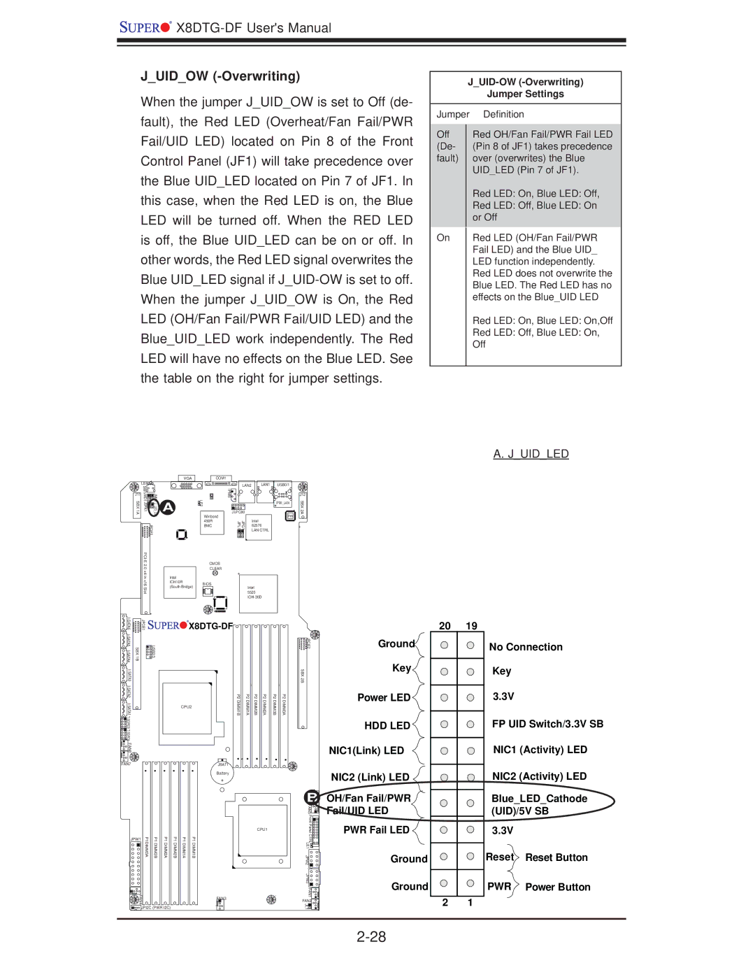
J_UID_OW (-Overwriting)
When the jumper J_UID_OW is set to Off (de- fault), the Red LED (Overheat/Fan Fail/PWR Fail/UID LED) located on Pin 8 of the Front Control Panel (JF1) will take precedence over the Blue UID_LED located on Pin 7 of JF1. In this case, when the Red LED is on, the Blue LED will be turned off. When the RED LED is off, the Blue UID_LED can be on or off. In other words, the Red LED signal overwrites the Blue UID_LED signal if
|
|
| VGA | COM1 |
|
|
|
|
| LE4 |
|
|
| LAN2 | LAN1 | USB0/1 |
|
SBX1A | SW1 | JUIDOWJNMI1 | A | LE2 | IPMBJLPC80 |
|
| SBX2A |
JWD1JSPK1 |
|
| ||||||
J11 |
|
|
|
|
|
|
| J12 |
|
|
|
|
|
|
| IPMI_LAN |
|
|
|
|
| Winbond |
| Intel | PHY |
|
|
| JPCIE3 |
| 450R | JPG1 JPL1 |
|
| |
|
|
| BMC | 82576 |
| + | ||
|
|
|
|
|
| LAN CTRL |
|
|
| CMOS | |
.0 |
| CLEAR |
x4 in |
| |
Intel |
| |
x16 | ICH10R | BIOS |
Slot | (South Bridge) | Intel |
| 5520 | |
|
|
J_UID-OW (-Overwriting)
Jumper Settings
Jumper | Definition | |
|
| |
Off |
| Red OH/Fan Fail/PWR Fail LED |
(De- |
| (Pin 8 of JF1) takes precedence |
fault) |
| over (overwrites) the Blue |
|
| UID_LED (Pin 7 of JF1). |
|
| Red LED: On, Blue LED: Off, |
|
| Red LED: Off, Blue LED: On |
|
| or Off |
|
|
|
On |
| Red LED (OH/Fan Fail/PWR |
|
| Fail LED) and the Blue UID_ |
|
| LED function independently. |
|
| Red LED does not overwrite the |
|
| Blue LED. The Red LED has no |
|
| effects on the Blue_UID LED |
|
| Red LED: On, Blue LED: On,Off |
|
| Red LED: Off, Blue LED: On, |
|
| Off |
|
|
|
A. J_UID_LED
| JPCIE1 | |
SBX 1B | USB2/3 | |
|
| |
|
| |
|
| |
|
| |
FAN8 |
|
|
FAN7


 X8DTG-DF


| P2 | P2 | P2 | P2 | P2 | P2 |
CPU2 | DIMM1B | DIMM1A | DIMM2B | DIMM2A | DIMM3B | DIMM3A |
|
|
|
|
|
|
JBAT1
| 20 | 19 |
JPCIE2 | Ground | No Connection |
SBX | Key | Key |
2B |
|
|
| Power LED | 3.3V |
| HDD LED | FP UID Switch/3.3V SB |
| NIC1(Link) LED | NIC1 (Activity) LED |
Battery
BFAN6
FAN5 |
NIC2 (Link) LED ![]()
OH/Fan Fail/PWR
Fail/UID LED
NIC2 (Activity) LED
Blue_LED_Cathode (UID)/5V SB
JPW1 | P1DIMM3A | P1DIMM3B | P1DIMM2A |
FAN4 |
|
|
|
![]()
![]()
![]() JPI2C (PWR I2C)
JPI2C (PWR I2C)
P1 DIMM2B
P1 DIMM1A
P1 DIMM1B
CPU1 |
FAN3
Front PanelCTRL |
|
LE1 |
|
JPW2 |
|
JPW3 |
|
FAN1 |
|
FAN2 | 4 |
JL1 | 1 |
|
PWR Fail LED ![]() Ground
Ground
Ground
2 1
3.3V
Reset Reset Button
PWR Power Button