Chapter 2: Installation
Front Control Panel
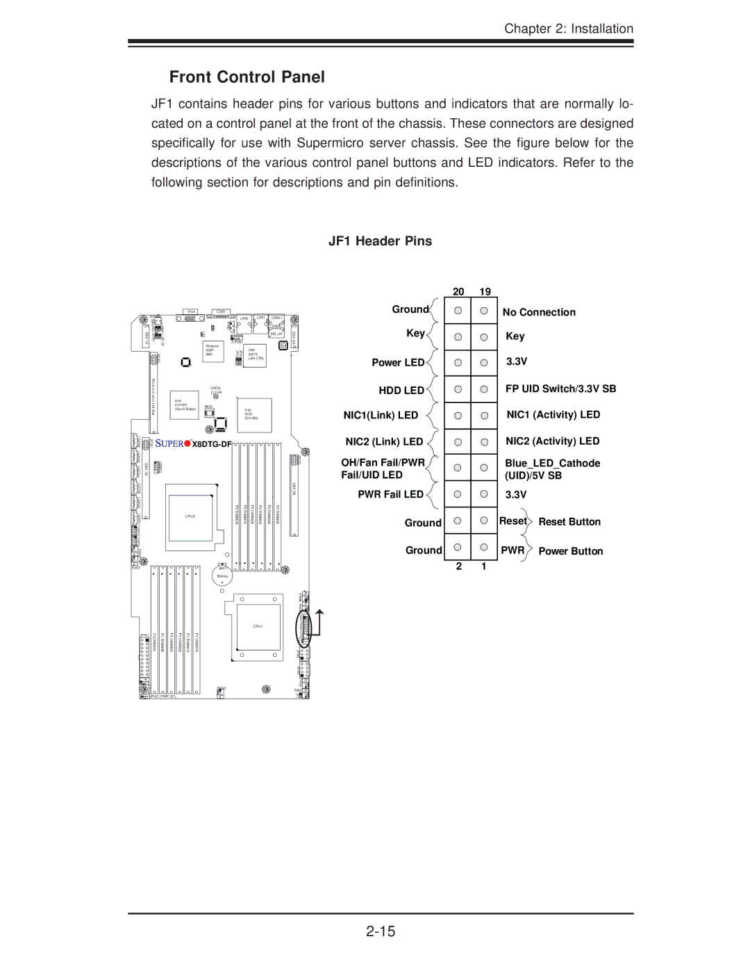
JF1 contains header pins for various buttons and indicators that are normally lo- cated on a control panel at the front of the chassis. These connectors are designed specifically for use with Supermicro server chassis. See the figure below for the descriptions of the various control panel buttons and LED indicators. Refer to the following section for descriptions and pin definitions.
JF1 Header Pins
LE4![]()
![]()
![]()
J11 | SW1 |
| |
JWD1 JSPK1 | JNMI1 J_UID_OW | ||
SBX 1A | |||
|
| JPCIE3 | |
|
|
VGA |
| COM1 |
|
|
|
|
|
| LAN2 | LAN1 | USB0/1 |
| |
| LE2 | IPMB |
|
|
| J12 |
|
|
|
| IPMI_LAN | SBX | |
|
|
|
|
|
| |
|
| JLPC80 |
|
| PHY | 2A |
| Winbond |
| Intel |
| ||
| 450R | JPG1 JPL1 |
|
|
| |
| BMC |
| 82576 |
| + | |
|
|
|
| LAN CTRL |
|
|
| CMOS |
|
|
|
| |
| CLEAR |
|
|
|
| |
Intel |
|
|
|
|
|
|
ICH10R | BIOS |
|
|
|
|
|
(South Bridge) |
| Intel |
|
| ||
|
|
|
| |||
|
|
| 5520 |
|
| |
|
|
|
|
| ||
Ground![]()
Key
Power LED ![]()
HDD LED
NIC1(Link) LED
20 | 19 |
No Connection
Key
3.3V
FP UID Switch/3.3V SB
NIC1 (Activity) LED
| JPCIE1 | |
SBX 1B | USB2/3 | |
|
| |
|
| |
|
| |
|
| |
FAN8 |
|
|
FAN7


 X8DTG-DF


| P2 | P2 | P2 | P2 | P2 | P2 |
CPU2 | DIMM1B | DIMM1A | DIMM2B | DIMM2A | DIMM3B | DIMM3A |
JBAT1
Battery
![]()
![]()
![]()
![]() JPCIE2 SBX 2B
JPCIE2 SBX 2B
NIC2 (Link) LED ![]()
OH/Fan Fail/PWR
Fail/UID LED
PWR Fail LED ![]()
Ground
Ground
2 1
NIC2 (Activity) LED
Blue_LED_Cathode (UID)/5V SB
3.3V
Reset Reset Button
PWR Power Button
JPW1 | P1DIMM3A | P1DIMM3B | P1DIMM2A |
FAN4 |
|
|
|
![]()
![]()
![]() JPI2C (PWR I2C)
JPI2C (PWR I2C)
P1 DIMM2B
P1 DIMM1A
P1 DIMM1B
CPU1 |
FAN3
FAN6 FAN5 |
|
Front PanelCTRL |
|
LE1 |
|
JPW2 |
|
JPW3 |
|
FAN1 |
|
FAN2 | 4 |
JL1 | 1 |
|