![]()
![]()
![]()
![]()
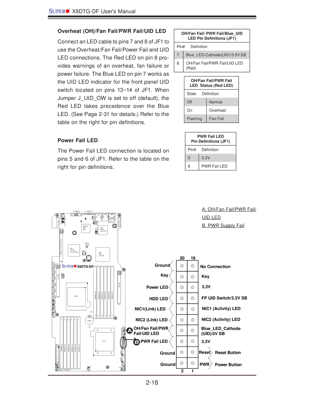
Overheat (OH)/Fan Fail/PWR Fail/UID LED
Connect an LED cable to pins 7 and 8 of JF1 to use the Overheat/Fan Fail/Power Fail and UID LED connections. The Red LED on pin 8 pro- vides warnings of an overheat, fan failure or power failure. The Blue LED on pin 7 works as the UID LED indicator for the front panel UID switch located on pins 13~14 of JF1. When Jumper J_UID_OW is set to off (default), the Red LED takes precedence over the Blue LED. (See Page
Power Fail LED
The Power Fail LED connection is located on pins 5 and 6 of JF1. Refer to the table on the right for pin definitions.
|
|
| VGA | COM1 |
|
|
|
|
| LE4 |
|
|
| LAN2 | LAN1 | USB0/1 |
|
SBX1A | W1S | JUIDOWJNMI1 | LE2 | IPMB |
|
|
| SBX2A |
WD1JJSPK1 |
|
|
| |||||
J11 |
|
|
|
|
|
|
| J12 |
|
|
|
|
|
|
| IPMI_LAN |
|
|
|
|
| Winbond | JLPC80 |
| PHY |
|
|
|
|
|
| Intel |
| ||
|
| JPCIE3 |
| 450R | JPG1 JPL1 |
|
| |
|
|
| BMC | 82576 |
| + | ||
|
|
|
|
|
| LAN CTRL |
|
|
OH/Fan Fail/ PWR Fail/Blue_UID
LED Pin Definitions (JF1)
Pin# Definition
7
8OH/Fan Fail/PWR Fail/UID LED (Red)
OH/Fan Fail/PWR Fail
LED Status (Red LED)
State Definition
Off | Normal | |
On | Overheat | |
Flashing | Fan Fail | |
|
|
PWR Fail LED
Pin Definitions (JF1)
Pin# Definition
53.3V
6PWR Fail LED
A.OH/Fan Fail/PWR Fail/
UID LED
B.PWR Supply Fail
| CMOS | |
.0 |
| CLEAR |
x4 in |
| |
Intel |
| |
x16 | ICH10R | BIOS |
Slot | (South Bridge) | Intel |
| 5520 | |
|
|
20 | 19 |
| JPCIE1 | |
SBX 1B | USB2/3 | |
|
| |
|
| |
|
| |
|
| |
FAN8 |
|
|


 X8DTG-DF


| P2 | P2 | P2 | P2 | P2 | P2 |
CPU2 | DIMM1B | DIMM1A | DIMM2B | DIMM2A | DIMM3B | DIMM3A |
|
| Ground | No Connection |
| JPCIE2 | Key | Key |
|
| ||
SBX 2B |
| Power LED | 3.3V |
|
|
HDD LED | FP UID Switch/3.3V SB |
NIC1(Link) LED | NIC1 (Activity) LED |
FAN7
JBAT1
Battery
| NIC2 (Link) LED |
FAN6 FAN5 | OH/Fan Fail/PWR |
A Fail/UID LED |
NIC2 (Activity) LED
Blue_LED_Cathode (UID)/5V SB
| P1DIMM3A | P1DIMM3B | P1DIMM2A | P1DIMM2B | P1DIMM1A | CPU1 |
JPW1 | P1DIMM1B |
FAN4 | FAN3 |
JPI2C (PWR I2C) |
|
Front Panel | B PWR Fail LED |
CTRL | |
LE1 |
|
JPW2 | Ground |
| |
JPW3 |
|
FAN1 | Ground |
FAN2 | 4 |
JL1 | 1 |
|
2 1
3.3V
Reset Reset Button
PWR Power Button