![]()
![]()
![]()
![]()
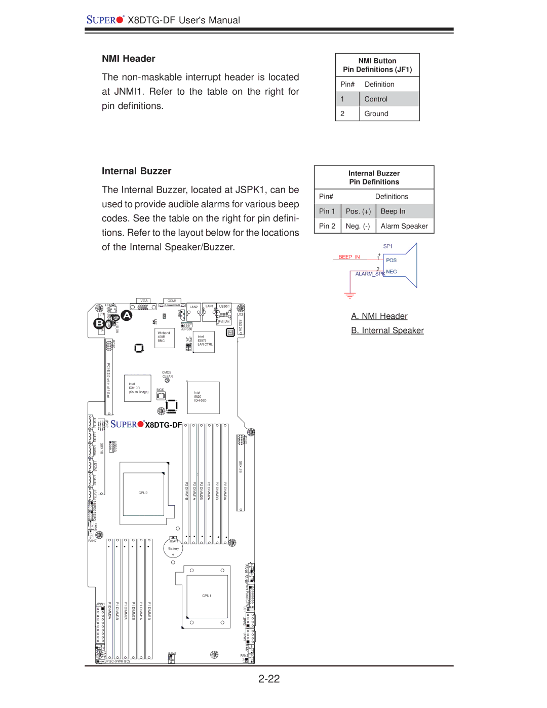
NMI Header
The
Internal Buzzer
The Internal Buzzer, located at JSPK1, can be used to provide audible alarms for various beep codes. See the table on the right for pin defini- tions. Refer to the layout below for the locations of the Internal Speaker/Buzzer.
NMI Button
Pin Definitions (JF1)
Pin# Definition
1Control
2Ground
Internal Buzzer
Pin Definitions
Pin# |
|
| Definitions | |
Pin 1 |
| Pos. (+) |
| Beep In |
|
| |||
Pin 2 |
| Neg. |
| Alarm Speaker |
|
| |||
|
|
|
|
|
|
| VGA | COM1 |
|
|
| LE4 |
|
| LAN2 | LAN1 |
1A | SW1 | JUIDOWJNMI1 | LE2 | IPMB |
|
JSPK1JWD1 |
| ||||
J11 |
| A |
|
|
|
BXS |
|
|
| JLPC80 |
|
|
|
| Winbond |
| Intel |
|
| JPCIE3 | 450R | JPG1 JPL1 | |
|
| BMC | 82576 | ||
|
|
|
|
| LAN CTRL |
|
| CMOS |
|
| |
| .0 |
| CLEAR |
|
|
| x4 in |
|
|
| |
| Intel |
|
|
| |
| x16 | ICH10R | BIOS | Intel | |
| Slot | (South Bridge) |
| ||
|
|
| 5520 | ||
|
|
|
| ||
USB0/1
![]()
![]() IPMI_LAN
IPMI_LAN
![]() PHY
PHY ![]()
J12
SBX 2A
+
A. NMI Header
B. Internal Speaker
| JPCIE1 | |
SBX 1B | USB2/3 | |
|
| |
|
| |
|
| |
|
| |
FAN8 |
|
|
FAN7
![]()
![]()
![]()
![]()
![]() X8DTG-DF
X8DTG-DF![]()
![]()
![]()
![]()
![]()
![]()
![]()
![]()
![]()
![]()
![]()
![]()
| P2 | P2 | P2 | P2 | P2 | P2 |
CPU2 | DIMM1B | DIMM1A | DIMM2B | DIMM2A | DIMM3B | DIMM3A |
JBAT1
Battery
![]()
![]()
![]()
![]() JPCIE2 SBX 2B
JPCIE2 SBX 2B
JPW1 | P1DIMM3A | P1DIMM3B | P1DIMM2A |
FAN4 |
|
|
|
![]()
![]()
![]() JPI2C (PWR I2C)
JPI2C (PWR I2C)
P1 DIMM2B
P1 DIMM1A
P1 DIMM1B
CPU1 |
FAN3
FAN6 FAN5 |
| |
Front PanelCTRL |
| |
LE1 |
| |
JPW2 |
| |
JPW3 |
| |
FAN1 |
| |
FAN2 | 4 | |
JL1 | ||
1 | ||
|