Chapter 2: Installation
NIC1 LED Indicator
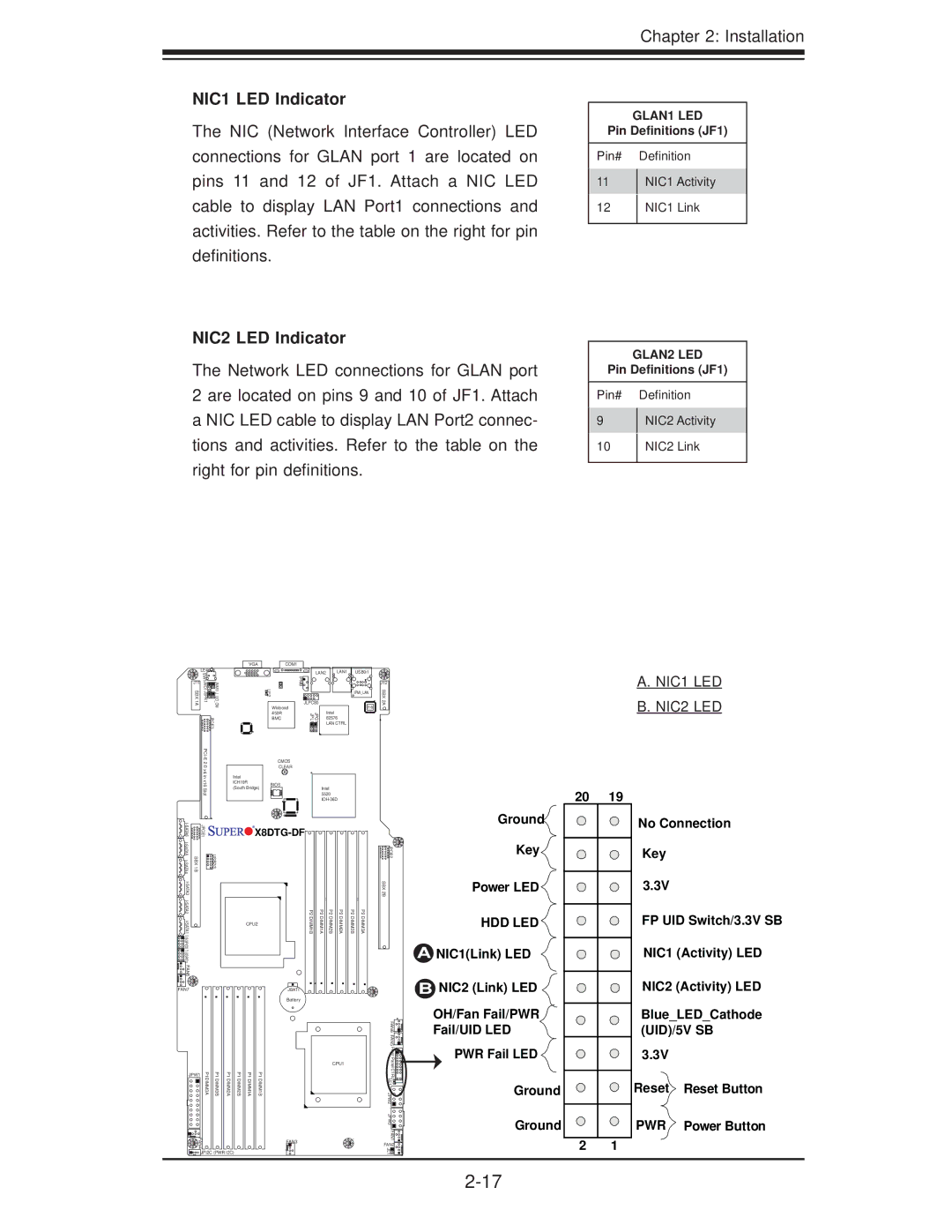
The NIC (Network Interface Controller) LED connections for GLAN port 1 are located on pins 11 and 12 of JF1. Attach a NIC LED cable to display LAN Port1 connections and activities. Refer to the table on the right for pin definitions.
NIC2 LED Indicator
The Network LED connections for GLAN port 2 are located on pins 9 and 10 of JF1. Attach a NIC LED cable to display LAN Port2 connec- tions and activities. Refer to the table on the right for pin definitions.
GLAN1 LED
Pin Definitions (JF1)
Pin# Definition
11NIC1 Activity
12NIC1 Link
GLAN2 LED
Pin Definitions (JF1)
Pin# Definition
9NIC2 Activity
10NIC2 Link
LE4![]()
![]()
![]()
J11 | SW1 |
| |
JWD1 JSPK1 | JNMI1 J_UID_OW | ||
SBX 1A | |||
|
| JPCIE3 | |
|
|
VGA | COM1 |
| LAN2 | LAN1 | USB0/1 |
|
LE2 | IPMB |
|
| J12 |
|
| IPMI_LAN | SBX | |
Winbond | JLPC80 |
| PHY | 2A |
| Intel |
| ||
450R | JPG1 JPL1 |
|
| |
BMC | 82576 |
| + | |
|
| LAN CTRL |
|
|
| CMOS |
| CLEAR |
Intel |
|
ICH10R | BIOS |
(South Bridge) | Intel |
| 5520 |
|
A. NIC1 LED B. NIC2 LED
| JPCIE1 | |
SBX 1B | USB2/3 | |
|
| |
|
| |
|
| |
|
| |
FAN8 |
|
|
FAN7


 X8DTG-DF


| P2 | P2 | P2 | P2 | P2 | P2 |
CPU2 | DIMM1B | DIMM1A | DIMM2B | DIMM2A | DIMM3B | DIMM3A |
|
|
|
|
|
|
JBAT1
Battery
![]()
![]()
![]()
![]() JPCIE2 SBX 2B
JPCIE2 SBX 2B
No Connection
Key
3.3V
FP UID Switch/3.3V SB
NIC1 (Activity) LED
NIC2 (Activity) LED
JPW1 | P1DIMM3A | P1DIMM3B | P1DIMM2A |
|
|
| |
FAN4 |
|
|
|
![]()
![]()
![]() JPI2C (PWR I2C)
JPI2C (PWR I2C)
P1 DIMM2B
P1 DIMM1A
P1 DIMM1B
CPU1 |
FAN3
FAN6 FAN5 |
|
Front PanelCTRL |
|
LE1 |
|
JPW2 |
|
JPW3 |
|
FAN1 |
|
FAN2 | 4 |
JL1 | 1 |
|
Ground
Key![]()
Power LED
HDD LED 
A NIC1(Link) LED
BNIC2 (Link) LED
OH/Fan Fail/PWR
Fail/UID LED
PWR Fail LED ![]()
Ground
Ground
2 1
Blue_LED_Cathode (UID)/5V SB
3.3V
Reset Reset Button
PWR Power Button
