TANDBERG 3G Gateway User Manual
1.1 The TANDBERG 3G Gateway
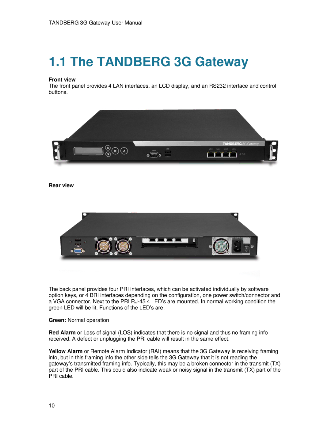
Front view
The front panel provides 4 LAN interfaces, an LCD display, and an RS232 interface and control buttons.
Rear view
The back panel provides four PRI interfaces, which can be activated individually by software option keys, or 4 BRI interfaces depending on the configuration, one power switch/connector and a VGA connector. Next to the PRI
Green: Normal operation
Red Alarm or Loss of signal (LOS) indicates that there is no signal and thus no framing info received. A defect or unplugging the PRI cable will result in the same effect.
Yellow Alarm or Remote Alarm Indicator (RAI) means that the 3G Gateway is receiving framing info, but in this framing info the other side tells the 3G Gateway that it is not reading the gateway’s transmitted framing info. Typically, this may be a broken connector in the transmit (TX) part of the PRI cable. This could also indicate weak or noisy signal in the transmit (TX) part of the PRI cable.
10