Trace Oxygen Analyzer | Installation | |
|
|
|
Fuse Installation: The fuse block, at the right of the power cord receptacle, accepts US or European size fuses. A jumper replaces the fuse in whichever fuse receptacle is not used. Fuses are not installed at the factory. Be sure to install the proper fuse as part of installation. (See Fuse Replacement in Chapter 5, Maintenance.)
3.3.2.2
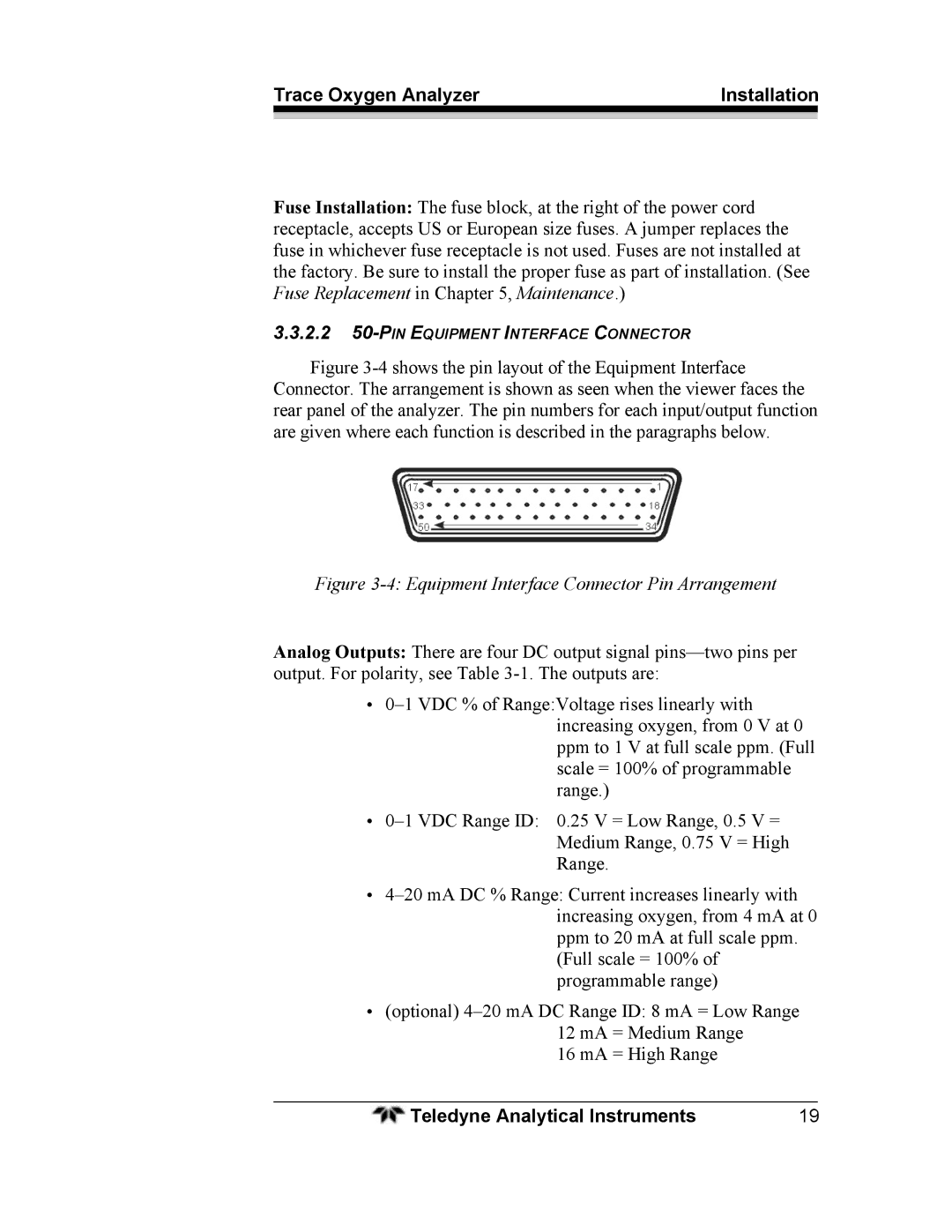
Figure 3-4 shows the pin layout of the Equipment Interface Connector. The arrangement is shown as seen when the viewer faces the rear panel of the analyzer. The pin numbers for each input/output function are given where each function is described in the paragraphs below.
Figure 3-4: Equipment Interface Connector Pin Arrangement
Analog Outputs: There are four DC output signal
•
•
•
•(optional)
16 mA = High Range
Teledyne Analytical Instruments | 19 |