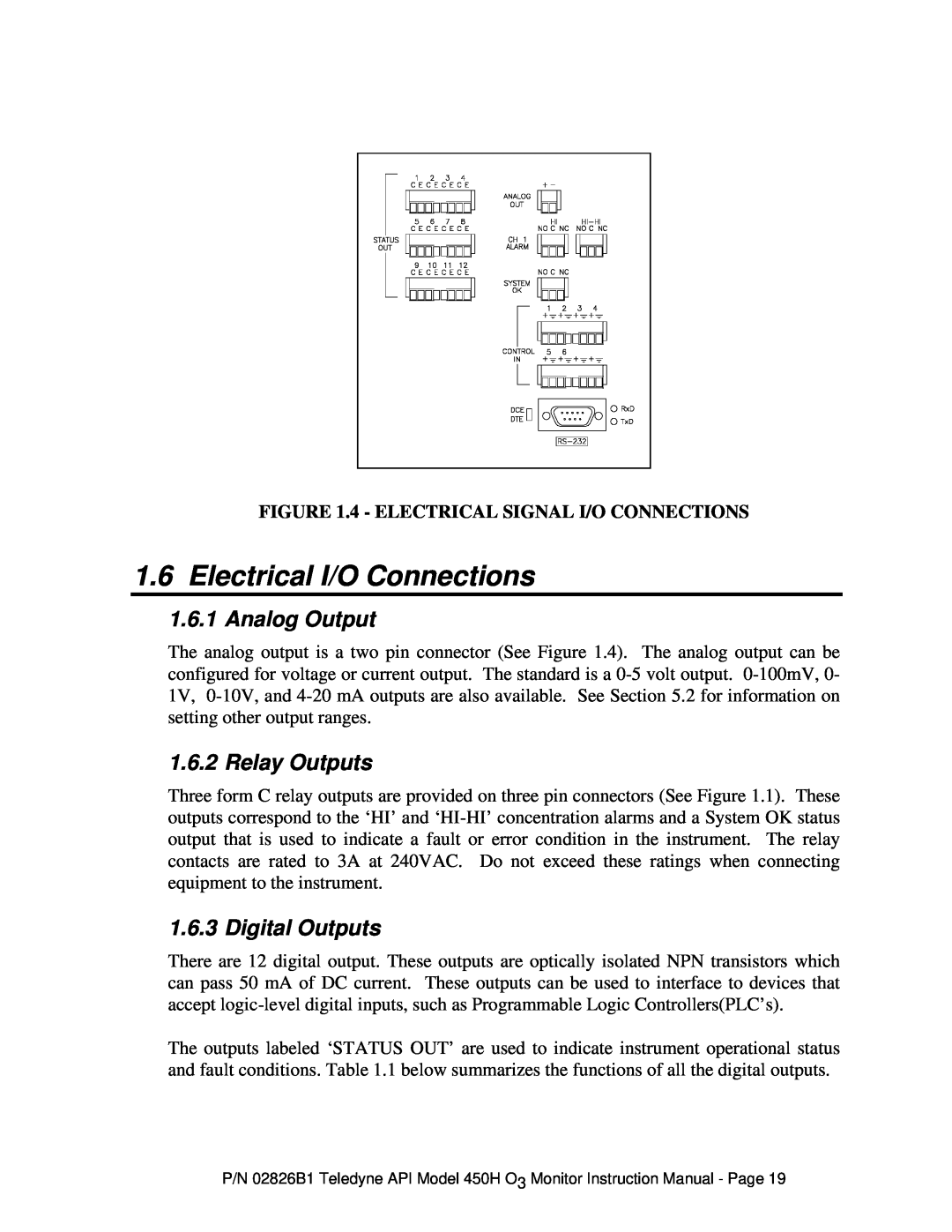
FIGURE 1.4 - ELECTRICAL SIGNAL I/O CONNECTIONS
1.6Electrical I/O Connections
1.6.1Analog Output
The analog output is a two pin connector (See Figure 1.4). The analog output can be configured for voltage or current output. The standard is a
1.6.2 Relay Outputs
Three form C relay outputs are provided on three pin connectors (See Figure 1.1). These outputs correspond to the ‘HI’ and
1.6.3 Digital Outputs
There are 12 digital output. These outputs are optically isolated NPN transistors which can pass 50 mA of DC current. These outputs can be used to interface to devices that accept
The outputs labeled ‘STATUS OUT’ are used to indicate instrument operational status and fault conditions. Table 1.1 below summarizes the functions of all the digital outputs.
P/N 02826B1 Teledyne API Model 450H O3 Monitor Instruction Manual - Page 19