2.2.2 Status LED’s
The three status LED’s to the right of the display indicate the general status of the Model 450H Monitor. The green SAMPLE LED indicates the sampling status. The yellow FAULT LED indicates the fault status. The red ALARM LED indicates the concentration alarm status. Table 2.4 below summarizes the meanings of the status LED’s.
LED |
| State |
| Meaning |
Green |
| Off |
| Not monitoring(1) |
|
| On | Monitoring normally | |
Yellow | Off | No warnings exist | ||
| Blinking | Warnings exist | ||
Red | Off | No Alarms active | ||
| Blinking | Alarms active | ||
(1) This occurs during all diagnostics modes |
| |||
TABLE 2.4 | STATUS LED'S |
| ||
2.3 Software Operation
This section describes the operation of the instrument software through the front panel interface described in the previous section. The instrument software has been designed to be easy to use, yet powerful enough to allow the user to customize the instrument for a particular application.
2.3.1 Main Menu
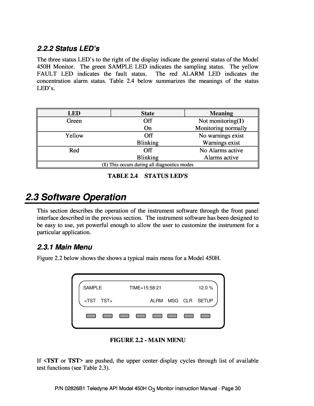
Figure 2.2 below shows the shows a typical main menu for a Model 450H.
SAMPLE |
| TIME=15:58:21 |
|
| 12.0 % | ||||||
|
|
|
|
|
|
|
|
|
|
|
|
<TST |
| TST> |
|
| ALRM |
| MSG CLR |
| SETUP | ||
|
|
|
|
|
|
|
|
|
|
|
|
FIGURE 2.2 - MAIN MENU
If <TST or TST> are pushed, the upper center display cycles through list of available test functions (see Table 2.3).
P/N 02826B1 Teledyne API Model 450H O3 Monitor Instruction Manual - Page 30
