| Part No. |
| June 2001 |
Page 12 of 34 |
Setting the Modem Card DIP Switch
An
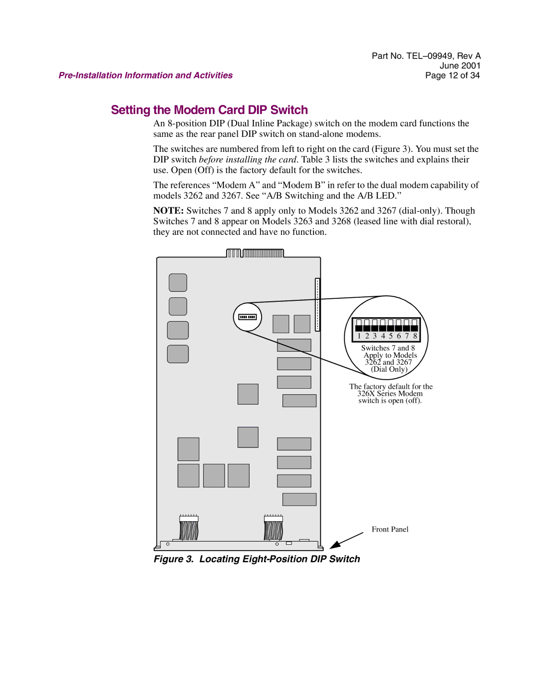
The switches are numbered from left to right on the card (Figure 3). You must set the DIP switch before installing the card. Table 3 lists the switches and explains their use. Open (Off) is the factory default for the switches.
The references “Modem A” and “Modem B” in refer to the dual modem capability of models 3262 and 3267. See “A/B Switching and the A/B LED.”
NOTE: Switches 7 and 8 apply only to Models 3262 and 3267
1 2 3 4 5 6 7 8
Switches 7 and 8
Apply to Models
3262 and 3267
(Dial Only)
The factory default for the 326X Series Modem switch is open (off).
Front Panel