Telenetics Modular Nest manual Filler Panels

Models: Modular Nest

1 34
Download 34 pages 2.62 Kb
Page 20
Image 20


Part No. TEL–09949, Rev A

Pre-Installation Information and Activities

June 2001

Page 20 of 34

Filler Panels

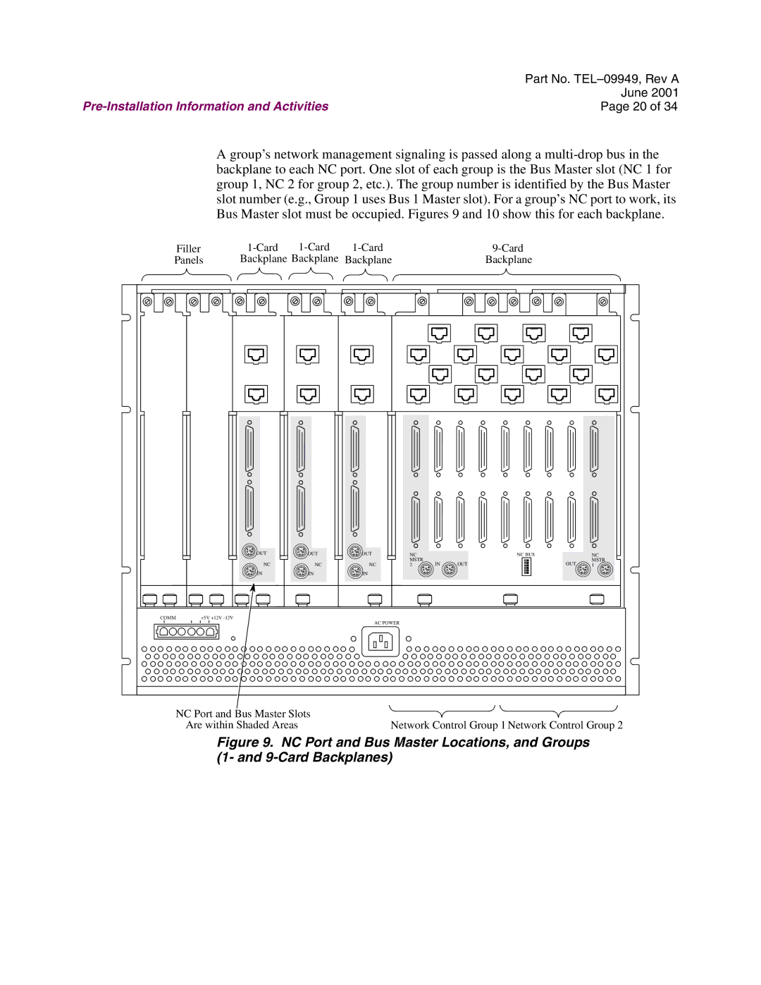
A group’s network management signaling is passed along a multi-drop bus in the backplane to each NC port. One slot of each group is the Bus Master slot (NC 1 for group 1, NC 2 for group 2, etc.). The group number is identified by the Bus Master slot number (e.g., Group 1 uses Bus 1 Master slot). For a group’s NC port to work, its Bus Master slot must be occupied. Figures 9 and 10 show this for each backplane.


1-Card


1-Card


1-Card


9-Card

Backplane Backplane

Backplane


Backplane


OUT

NC

IN

OUT

NC

IN

OUT

NC

IN

NC


NC BUS

MSTR

IN

OUT

2

NC

MSTR

OUT 1

COMM

+5V +12V -12V

AC POWER

NC Port and Bus Master Slots


Are within Shaded Areas

Network Control Group 1Network Control Group 2

Figure 9. NC Port and Bus Master Locations, and Groups (1- and 9-Card Backplanes)

Page 20
Image 20
Telenetics Modular Nest manual Filler Panels