| Part No. |
| June 2001 |
Page 11 of 34 |
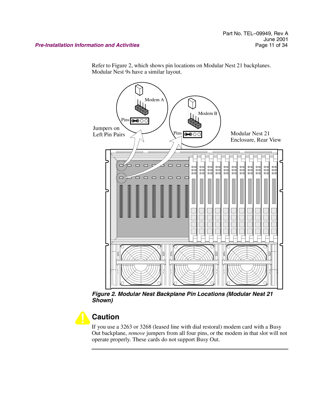
Refer to Figure 2, which shows pin locations on Modular Nest 21 backplanes.
Modular Nest 9s have a similar layout.
Modem A
Modem B
Pins |
|
Jumpers on | Pins |
Left Pin Pairs |
Modular Nest 21 Enclosure, Rear View
Figure 2. Modular Nest Backplane Pin Locations (Modular Nest 21 Shown)
![]()
![]() Caution
Caution
If you use a 3263 or 3268 (leased line with dial restoral) modem card with a Busy Out backplane, remove jumpers from all four pins, or the modem in that slot will not operate properly. These cards do not support Busy Out.