| Part No. |
| June 2001 |
Page 23 of 34 |
| A8 |
| A6 |
| A4 |
| A2 |
|
|
|
|
DIAL LINE A |
|
|
|
|
|
|
|
|
|
|
|
2W LEASE |
|
|
|
|
|
|
|
|
|
|
|
A9 |
| A7 |
| A5 |
| A3 |
| A1 |
|
|
|
| B8 |
| B6 |
| B4 |
| B2 |
|
|
|
|
DIAL LINE B |
|
|
|
|
|
|
|
|
|
|
|
2W/4W LEASE |
|
|
|
|
|
|
|
|
|
|
|
B9 |
| B7 |
| B5 |
| B3 |
| B1 |
|
|
|
SLOT9 | 8 | 7 | 6 | 5 | 4 | 3 | 2 | 1 |
|
|
|
|
|
|
|
|
|
|
|
| Bus Master | ||
A | A | A | A | A | A | A | A | A | Switch | ||
|
|
| |||||||||
DTE | DTE | DTE | DTE | DTE | DTE | DTE | DTE | DTE |
|
|
|
B | B | B | B | B | B | B | B | B | NMS BUS | ||
|
|
|
|
|
|
|
|
| |||
|
|
|
|
|
|
|
|
| 2 | 6 | 1 |
|
|
|
|
|
|
|
|
| 1 | 5 | 2 |
|
|
|
|
|
|
|
|
| 1 | 4 | 2 |
|
|
|
|
|
|
|
|
| 1 | 3 | 2 |
|
|
|
|
|
|
|
|
| 1 | 2 | 2 |
|
|
|
|
|
|
|
|
| 1 | 1 | 2 |
NC |
|
|
| NC BUS |
|
| NC |
|
|
| |
MSTR | IN | OUT |
|
|
|
| OUT | MSTR |
|
|
|
2 |
|
|
|
| 1 |
|
|
| |||
COMM | +5V +12V |
|
|
|
|
| NC Port and | ||||
|
|
|
|
| AC POWER |
|
| Bus Master Locations | |||
|
|
|
|
|
|
|
|
| |||
|
|
|
|
|
|
|
|
| Are within Shaded Areas | ||
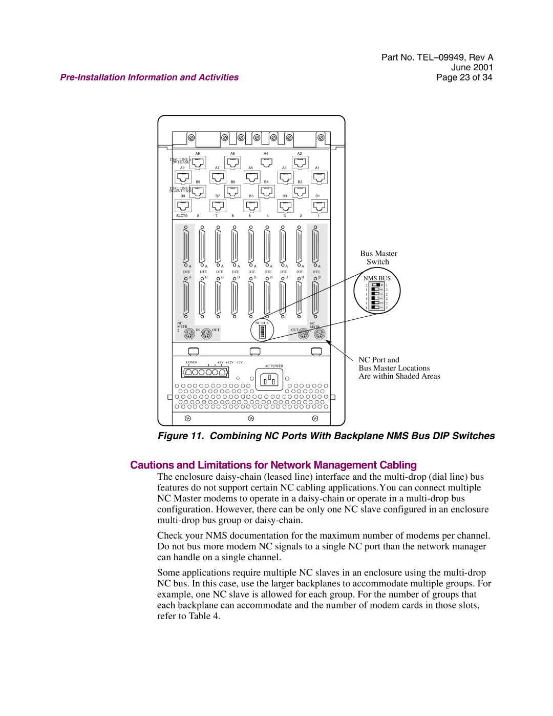
Figure 11. Combining NC Ports With Backplane NMS Bus DIP Switches
Cautions and Limitations for Network Management Cabling
The enclosure
Check your NMS documentation for the maximum number of modems per channel. Do not bus more modem NC signals to a single NC port than the network manager can handle on a single channel.
Some applications require multiple NC slaves in an enclosure using the
