| Part No. |
| June 2001 |
Page 16 of 34 |
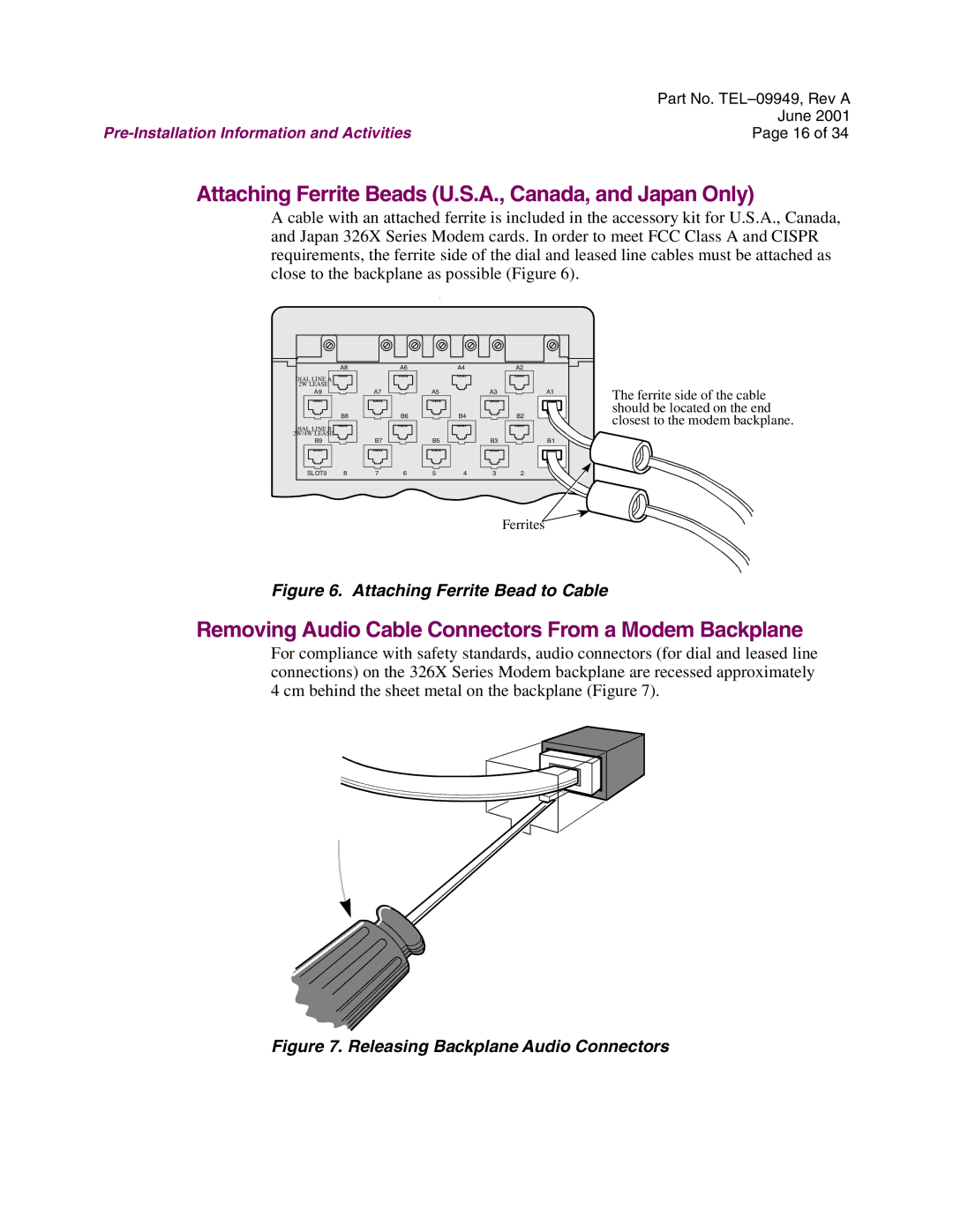
Attaching Ferrite Beads (U.S.A., Canada, and Japan Only)
A cable with an attached ferrite is included in the accessory kit for U.S.A., Canada, and Japan 326X Series Modem cards. In order to meet FCC Class A and CISPR requirements, the ferrite side of the dial and leased line cables must be attached as close to the backplane as possible (Figure 6).
|
|
|
| . |
|
|
|
|
|
| A8 |
| A6 |
| A4 |
| A2 |
|
|
DIAL LINE A |
|
|
|
|
|
|
|
|
|
2W LEASE |
|
|
|
|
|
|
|
| The ferrite side of the cable |
A9 |
| A7 |
| A5 |
| A3 |
| A1 | |
|
|
|
|
|
|
|
|
| |
|
|
|
|
|
|
|
|
| should be located on the end |
| B8 |
| B6 |
| B4 |
| B2 |
| closest to the modem backplane. |
DIAL LINE B |
|
|
|
|
|
|
|
| |
2W/4W LEASE |
|
|
|
|
|
|
|
|
|
B9 |
| B7 |
| B5 |
| B3 |
| B1 |
|
SLOT9 | 8 | 7 | 6 | 5 | 4 | 3 | 2 |
|
|
|
|
|
|
|
|
| Ferrites |
|
|
Figure 6. Attaching Ferrite Bead to Cable
Removing Audio Cable Connectors From a Modem Backplane
For compliance with safety standards, audio connectors (for dial and leased line connections) on the 326X Series Modem backplane are recessed approximately 4 cm behind the sheet metal on the backplane (Figure 7).