Connectors and Jumpers
This section provides information about the connector pinouts on the termination interface card and jumper settings on the backplane printed circuit board for your DEU subsystem.
Co n n e c t o rs
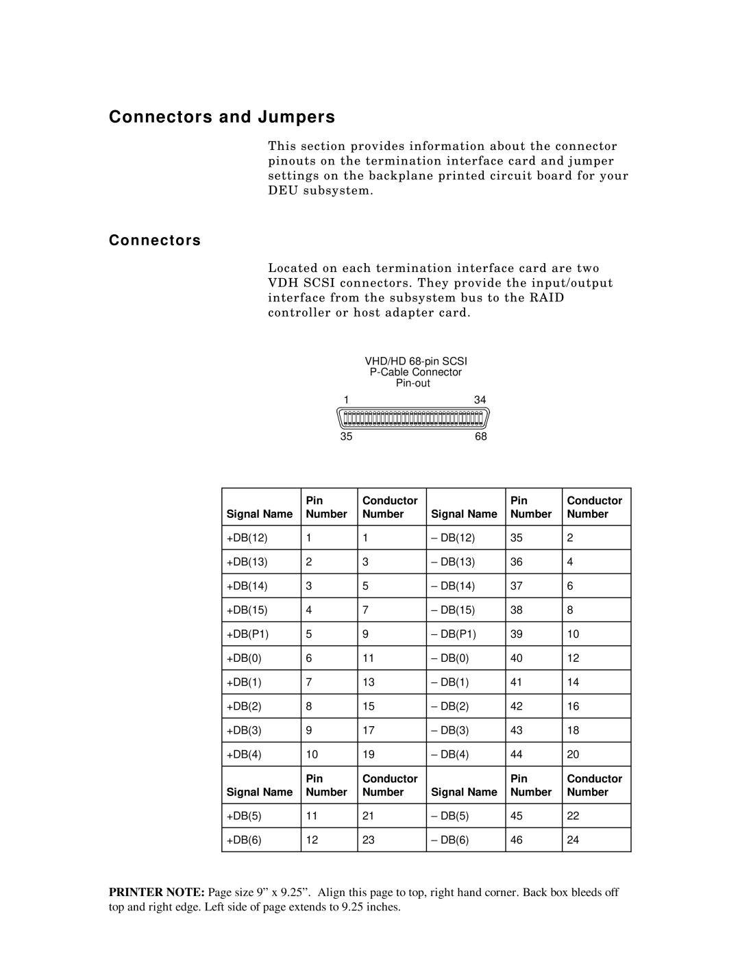
Located on each termination interface card are two VDH SCSI connectors. They provide the input/output interface from the subsystem bus to the RAID controller or host adapter card.
VHD/HD
| |
1 | 34 |
35 | 68 |
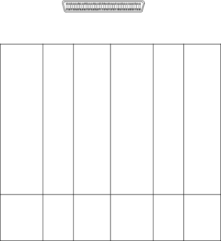
| Pin | Conductor |
| Pin | Conductor |
Signal Name | Number | Number | Signal Name | Number | Number |
|
|
|
|
|
|
+DB(12) | 1 | 1 | – DB(12) | 35 | 2 |
|
|
|
|
|
|
+DB(13) | 2 | 3 | – DB(13) | 36 | 4 |
|
|
|
|
|
|
+DB(14) | 3 | 5 | – DB(14) | 37 | 6 |
|
|
|
|
|
|
+DB(15) | 4 | 7 | – DB(15) | 38 | 8 |
|
|
|
|
|
|
+DB(P1) | 5 | 9 | – DB(P1) | 39 | 10 |
|
|
|
|
|
|
+DB(0) | 6 | 11 | – DB(0) | 40 | 12 |
|
|
|
|
|
|
+DB(1) | 7 | 13 | – DB(1) | 41 | 14 |
|
|
|
|
|
|
+DB(2) | 8 | 15 | – DB(2) | 42 | 16 |
|
|
|
|
|
|
+DB(3) | 9 | 17 | – DB(3) | 43 | 18 |
|
|
|
|
|
|
+DB(4) | 10 | 19 | – DB(4) | 44 | 20 |
| Pin | Conductor |
| Pin | Conductor |
Signal Name | Number | Number | Signal Name | Number | Number |
|
|
|
|
|
|
+DB(5) | 11 | 21 | – DB(5) | 45 | 22 |
|
|
|
|
|
|
+DB(6) | 12 | 23 | – DB(6) | 46 | 24 |
PRINTER NOTE: Page size 9” x 9.25”. Align this page to top, right hand corner. Back box bleeds off top and right edge. Left side of page extends to 9.25 inches.