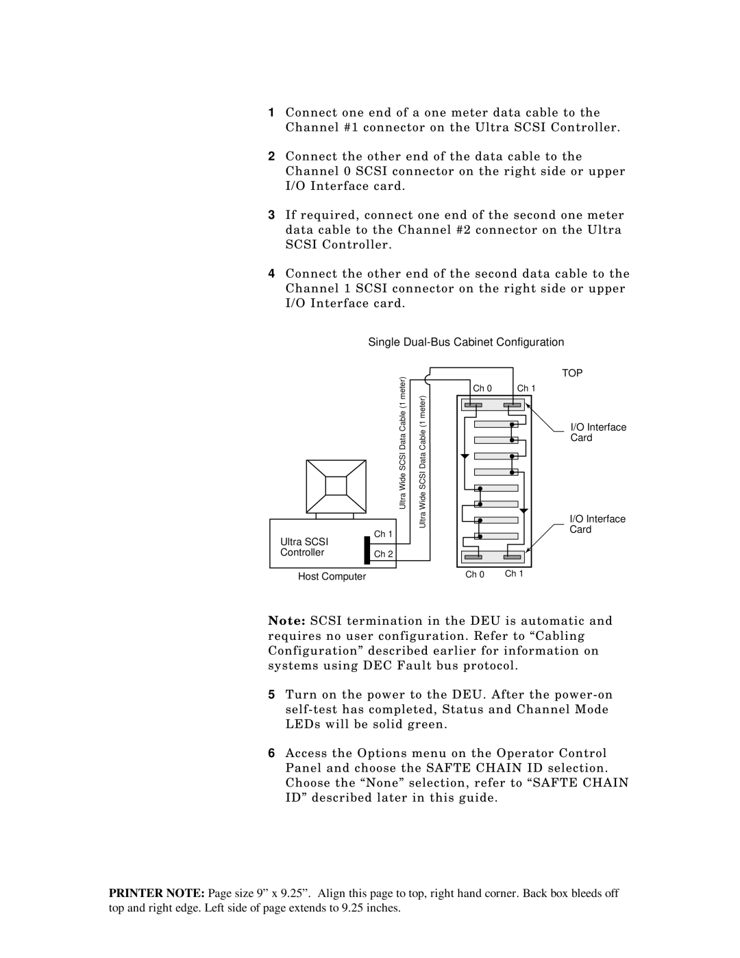
1Connect one end of a one meter data cable to the Channel #1 connector on the Ultra SCSI Controller.
2Connect the other end of the data cable to the Channel 0 SCSI connector on the right side or upper I/O Interface card.
3If required, connect one end of the second one meter data cable to the Channel #2 connector on the Ultra SCSI Controller.
4Connect the other end of the second data cable to the Channel 1 SCSI connector on the right side or upper I/O Interface card.
Single Dual-Bus Cabinet Configuration
meter)(1
Ultra SCSIWide CableData
|
|
|
|
|
|
|
Ultra SCSI |
| Ch 1 |
| |||
|
|
| ||||
|
|
| ||||
Controller |
| Ch 2 |
| |||
|
|
|
|
|
|
|
|
|
|
|
|
|
|
Host Computer
meter)(1
Ultra SCSIWide CableData
| TOP |
Ch 0 | Ch 1 |
| I/O Interface |
| Card |
| I/O Interface |
| Card |
Ch 0 | Ch 1 |
Note: SCSI termination in the DEU is automatic and requires no user configuration. Refer to “Cabling Configuration” described earlier for information on systems using DEC Fault bus protocol.
5Turn on the power to the DEU. After the
6Access the Options menu on the Operator Control Panel and choose the SAFTE CHAIN ID selection. Choose the “None” selection, refer to “SAFTE CHAIN ID” described later in this guide.
PRINTER NOTE: Page size 9” x 9.25”. Align this page to top, right hand corner. Back box bleeds off top and right edge. Left side of page extends to 9.25 inches.